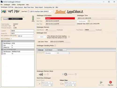
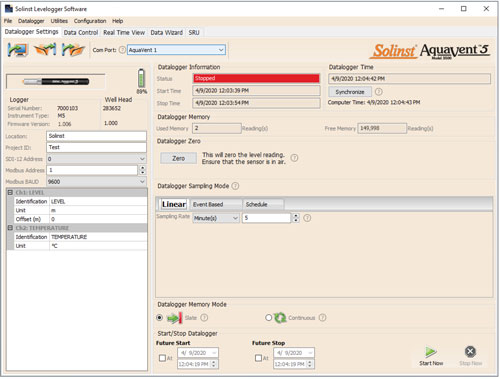
After you start Levelogger Software, the Main Window will appear, with the Datalogger Settings tab open.
Select the appropriate device from the centre Com Port drop-down menu.
Click ![]() to retrieve the current settings from the connected datalogger.
to retrieve the current settings from the connected datalogger.
Note:
Click on ![]() icons to get an explanation of that software feature.
icons to get an explanation of that software feature.

Figure 4-1 Dataloggers Settings Tab - LevelVent 5

Figure 4-2 Dataloggers Settings Tab - AquaVent 5
Note:
After retrieving the settings, If the Wellhead batteries have drained to 20% charge or lower, a warning message will appear to replace the batteries.
4.1 Datalogger Settings
After you have retrieved the settings of the connected datalogger, the Datalogger Settings tab will identify the Instrument Type, Serial Numbers, Firmware Version(s), Project ID, Location, and the Channel Settings.
- Instrument Type: will display the model of the attached datalogger, i.e.: M5
- Serial Numbers: the unique serial number of the attached logger will be displayed. If an AquaVent is connected, the serial number of the Wellhead will also be displayed.
- Firmware Versions: shows the firmware version of the connected logger. If an AquaVent is connected, the firmware version of the Wellhead will also be displayed.
- Project ID: input your own identification system. The Project ID is limited to 32 characters.
- Location: input specific site / location information. The location is limited to 32 characters.
The MODBUS and SDI-12 Address, and Baud Rate settings are only for use when using the SDI-12/MODBUS Interface Cables. See separate User Guides for communication using MODBUS and SDI-12 protocols.
4.1.1 Setting Up Channel Information
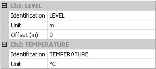
In the lower left portion of the Datalogger Settings tab is the area for setting channel parameters (level, temperature). The software will detect the available channels when the datalogger settings are retrieved.
4.1.1.1 Level Channel (Ch1)
- Identification describes the measurement parameter of the channel and has already been configured as 'LEVEL'. The channel can be re-named to suit each project. The channel monitors water column equivalent pressure. The Identification field will be the channel heading, data column heading and graph line name when viewing the data. Identification is limited to 32 characters.
- Unit refers to the channel's unit of measurement. There are six options for water level measurement: m (default), cm, ft, kPa, bar, and psi.
Note:
Readings can be converted to other units using the Data Wizard.
- Offset refers to an adjustment, such as the distance between the tip of the logger and the monitoring well cap or static water level. It is recommended that the value of 0.00 be used, as this keeps all subsequent readings relative to the tip of the logger. The reference range is -300 m to 5000 m or -1000 to 16,400 ft.
Note:
Readings can be corrected or offset with respect to a specific reference elevation or datum for a much wider spectrum of numeric offsets as part of the Data Wizard.

Figure 4-3 Datalogger Channel Setup
4.1.1.2 Temperature Channel (Ch2)
- Identification describes the measurement parameter of the channel and has already been configured as 'TEMPERATURE'. The channel can be re-named to suit each project. The Identification field will be the channel heading, data column heading and graph line name when viewing the data. Identification is limited to 32 characters.
- Unit refers to the channel's unit of measurement. The temperature channel can be set to °C (default) or ºF.


