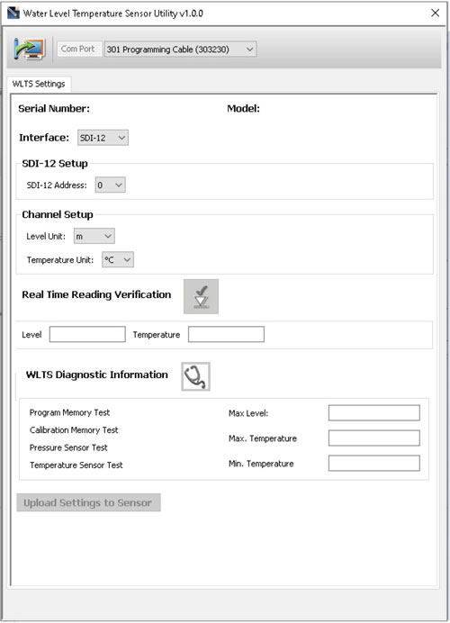
Figure 2-3 Water Level Temperature Sensor Utility
With the Sensor connected to the PC with the USB-A Programming Cable and the WLTS Utility started, select the appropriate Com Port for the connected WLTS from the drop-down menu.
Click the 'Retrieve Settings' icon ![]() . This will retrieve and display the current programmed settings for the connected WLTS, as well as the serial number, firmware version, and model.
. This will retrieve and display the current programmed settings for the connected WLTS, as well as the serial number, firmware version, and model.
Note:
The Model number (e.g. M5) refers to the maximum depth of submergence in meters below water, for that device. The 'A' indicates an absolute sensor, while a 'V' indicates a vented sensor.
You can now customize the WLTS protocol and measurement parameter settings. Select SDI-12 from the Interface drop-down.
SDI-12 settings include the Address (The address can be customized to any value from "0" to "9", "A" to "Z", or "a" to "z", giving a total of 62 unique addresses).
Note:
Without setting a specific address, the WLTS will power up with a default SDI-12 device address of 0. The communication settings for the WLTS comply with the SDI-12 standard at 1200 baud, 1 start bit, 7 data bits, 1 parity bit (even parity), and 1 stop bit.
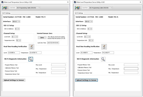
Set the units that the WLTS will be measuring in for the Level and Temperature Channels. For vented sensors, you can also perform a "Vented Sensor Zero" in air. Click Zero, you will receive a confirmation that the sensor has been zeroed. Click OK.
The parameters that were changed will be indicated by a blue highlight. When finished, click Upload Settings To Sensor. You will receive a confirmation message that the settings were uploaded. Click OK.

Figure 2-4 SDI-12 Settings – Vented and Absolute
To test that the Sensor is reading correctly before connecting it to the Communication/Vented Cable for deployment, you can click the 'Real Time Reading Verification' icon ![]() to obtain real-time readings from the Sensor.
to obtain real-time readings from the Sensor.
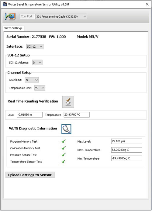
If further Diagnostic Information is required, click the 'WLTS Diagnostics Information' icon ![]() to perform a series of tests (Memory and Sensor) and obtain Level and Temperature information that may be helpful when troubleshooting any issues. Take a screenshot of this information to share for troubleshooting support.
to perform a series of tests (Memory and Sensor) and obtain Level and Temperature information that may be helpful when troubleshooting any issues. Take a screenshot of this information to share for troubleshooting support.

Figure 2-5 Water Level Temperature Sensor Diagnostic Information


