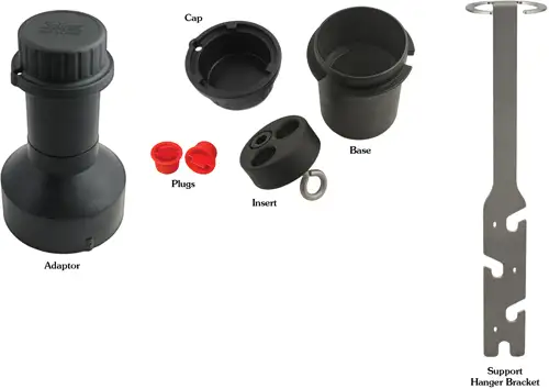
Solinst offers an optional Support Hanger Bracket and a 2" Well Cap Assembly, which consists of an insert, well cap base and well cap.
The 2" Well Cap Assembly insert has two openings which can optionally be used to install the Communication Cable. The second opening can be used to take manual water level measurements while the Water Level Temperature Sensor is recording down-well. When the openings are not in use, two red plugs are supplied with the assembly.
Note:
A third 0.7" ID access hole allows additional monitoring equipment in the well, such as a Water Level Meter for manual field measurements.
Note:
To accommodate 4" wells, a separate Adaptor is available for use with the 2" well cap base.

Figure 3-3 2" Well Cap Assembly, Adaptor, and Support Hanger Bracket
The following steps provide some guidance on how to install the Water Level Temperature Sensor using the Support Hanger Bracket and 2" Well Cap Assembly:
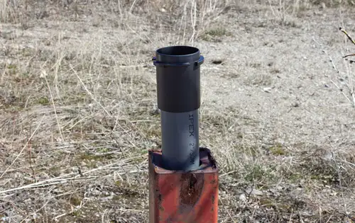
- Slide the well cap base onto the well casing. Do not secure it at this point.
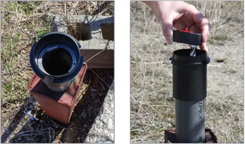
- Place the Support Hanger Bracket in the well cap base so it seats on the shoulder in the base. Place the insert into the well cap base.
- Remove one of the red plugs from the insert. Lower the WLTS connected to the Communication Cable through the opening and down the well until the wires at the top of the cable are above the insert. Remove the other red plug from the insert and take a manual depth to water measurement for your records.
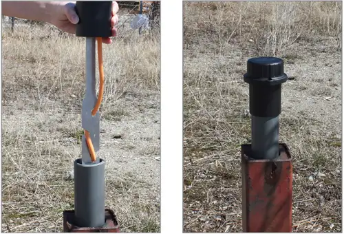
- Lift the well cap base with Support Hanger Bracket and insert from the well casing. Wrap the Communication Cable around the Support Hanger Bracket and slide into the cutouts to secure the cable to the bracket.
- Lower the well cap assembly back onto the well casing. Secure the well cap base to the well casing if desired. Install the well cap when the WLTS is not in use.


Note:
There are three holes in the top of the Support Hanger Bracket that can be used to secure it in the well cap base with screws.
Note:
The holes in the bracket can accommodate twist ties or zip ties to secure the cable to the bracket if desired.


