In the lower portion of the Datalogger Information screen is the window for setting channel parameters. The software will detect the available channels when the Datalogger Information settings are read.
The Level Channel
- Identification describes the measurement parameter of the channel and has already been configured as 'LEVEL'. The Level Channel monitors water column equivalent pressure. The Identification field will be the data column heading and graph line name when viewing the data.
- Units refers to the channel's units of measurement. There are six units of measure available for the user to select: m (default), cm, ft, kPa, mbar, and psi. When using a Barologger 5, the options are kPa (default), mbar, and psi. (There fewer options for Levelogger Gold and Junior Models).
- Offset refers to an offset correction, such as the distance between the tip of the datalogger and the monitoring well cap or static water level. It is recommended that the value of 0.00 be used for offset as this keeps all subsequent readings relative to the tip of the datalogger. The offset range is -1000 to 16400 ft or -300 m to 5000 m.
The Temperature Channel
- Identification describes the measurement parameter of the channel and has already been configured as 'TEMPERATURE'
- Units refers to the channel's units of measurement. The temperature channel can be set to ºC (default) or ºF. (Some Levelogger Gold Models measure in ºC only).

Figure 4-6 Temperature Channel
The Conductivity Channel
The conductivity channel will only be shown for the Levelogger 5 LTC, LTC Levelogger Edge and LTC Levelogger Junior.
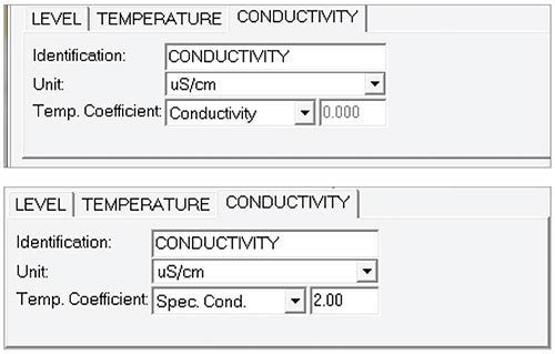
- Identification describes the measurement parameter of the channel and has already been configured as 'Conductivity'. The Identification field will be the channel heading, data column heading and graph line name when viewing the data.
- Unit refers to the channel's units of measurement. There are two units of measure available for the user to select: mS/cm or μS/cm.
- Temperature Coefficient (for LTC Levelogger Junior only) allows you to choose the actual conductivity ('Conductivity') at the current temperature or select Specific Conductance ('Spec. Cond'.) measurement in which the conductivity reading is temperature compensated to the standard of 25ºC. The Temperature Coefficient default is 2.00 for Specific Conductance readings. The Temperature Coefficient should not be adjusted, unless you know the value specific to the solution you are measuring.

Figure 4-7 Conductivity Channel
Rainlogger Measurement Parameters
Note:
You must program your Rainloggers in order to enter a Rainfall Cal Constant (the amount of rainfall per tip of the rain gauge), but you do not have to set them to record independently.
There is one channel of measurement for Rainloggers. The 'RainFall' Channel records each tip time by the connected tipping-bucket and outputs the amount of rainfall per tip (input Rainfall Cal Constant). When an STS reports Rainlogger data to the Home Station, it will send the accumulated rainfall amount per sample period (based on STS Sample Rate). To determine the exact time that a tip occurred, the Rainlogger would have to be set to record in its own internal memory, which stores each tip event.
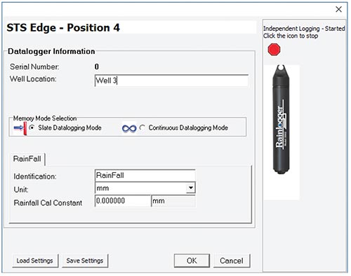
- Identification describes the measurement parameter of the channel and has already been configured as 'RainFall'. The channel can be re-named to suit each project. The Identification field will be the channel heading, data column heading and graph line name when viewing the data. Identification is limited to 32 characters.
- Units refers to the channel's unit of measurement. There are two units of measure available for the user to select: mm or in.
- The Rainfall Cal Constant field allows you to enter the calibration factor for the tipping-bucket you will be using. The calibration factor is the amount of rainfall depth (mm, in) per tip. The calibration factor should be indicated on a label on the tipping-bucket device or in the manufacturer's documentation. Input the calibration factor in mm or inches.

Figure 4-8 Rainlogger Settings
Note:
When an STS reports Rainlogger data to the Home Station, it will send the accumulated rainfall per sample period (based on STS Sample Rate).
After filling out the required fields, click Save Settings and OK to apply the information. The Datalogger Setup window will again be shown.
Continue entering information for each of the attached dataloggers. When each datalogger has been programmed, click Next on the Datalogger Setup window. The Alarms Setup window will open.


