RRL Radio Telemetry System Quick Start Guide


RRL 5 Remote Radio Link Station
System Components (2.4 GHz)
- Antenna
- USB-C Connection Access
- LED Activity Light
- Datalogger Connection
- Internal Barometer
1) Getting Started
Before you start programming your RRL Network, decide if you are going to configure and start all of your hardware in the office, or out in the field. Our recommended method is to set all hardware up in the office to ensure the RRL 5 Stations and connected dataloggers are communicating as programmed, before installation. However, you must remember to keep a record of each RRL 5 Station and the position and serial numbers of each connected datalogger, to ensure when in the field, you connect all hardware as programmed. This guide will take you through the recommended steps to set up your RRL 5 Network.
2) Install the Batteries
A RRL 5 uses six 1.5V AA user-replaceable lithium batteries. To install the batteries:
- Use a Phillips screwdriver to remove the three screws from the top of the RRL 5. Pull the top cap off.
- Use the screwdriver to remove the two screws holding the battery compartment cover and pull to remove the cover.
- Note the positive (+) and negative (–) etchings on the RRL. Install three batteries with the positive ends up
in the opening with the positive (+) etching. Install the other three batteries with the negative (-) ends up. - Replace the battery compartment cover and top cap.

Battery Life Estimates (6 x 3.6V AA lithium batteries at 1 Watt)
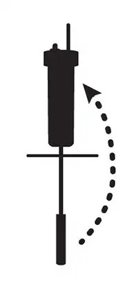
3) Connect the Antenna
To attach the antenna, line up the cable connector and screw it onto the antenna jack. See Section 9 for more information on installing the antenna when using the 2″ well cap assembly.

4) Connect Dataloggers
Each RRL 5 has a single port to connect one datalogger, or a Splitter. A Splitter provides a second
datalogger connection.
- Ensure the pins are lined up, and connect the Reader Cable directly to the RRL 5 or Splitter.
- Connect the Reader Cable to a Direct Read Cable with a Levelogger 5 connected, or to a
LevelVent 5 Wellhead. - Record the serial number of each datalogger, as well as the reference position connection to the
RRL 5.

Note:
When using a Splitter, the number 1 or 2 will identify the dataloggers in Solinst Telemetry Software. The numbers are labeled directly on the Splitter.

Remote Radio Link System Setup
- Direct Read Cable
- Levelogger
- Reader Cable
5) Install the Software
The Solinst Telemetry Software includes one main program and two utility programs:
![]() STS/RRL Administrator Software: used to set up new RRL 5 (or STS 5) Networks, edit existing networks (remote updates), and view data sent from each RRL 5 Station.
STS/RRL Administrator Software: used to set up new RRL 5 (or STS 5) Networks, edit existing networks (remote updates), and view data sent from each RRL 5 Station.
![]() STS/RRL Communication Agent: used to view network activity. Communication from each Remote RRL 5 Station to the Home Station is logged.
STS/RRL Communication Agent: used to view network activity. Communication from each Remote RRL 5 Station to the Home Station is logged.
Note:
The Communication Agent must remain open at all times during RRL 5 Network operation.
![]() RRL Remote Utility: provides a convenient way to communicate with programmed RRL 5 Stations in your office or in the field, as well as perform diagnostic checks and firmware upgrades.
RRL Remote Utility: provides a convenient way to communicate with programmed RRL 5 Stations in your office or in the field, as well as perform diagnostic checks and firmware upgrades.
Web Download
Download the newest version of Solinst Telemetry Software and the RRL Remote Utility by visiting
https://downloads.solinst.com
The STS/RRL Communication Agent automatically installs with the STS/RRL Administrator.
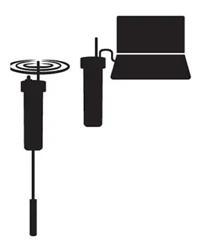
6) Connect RRL 5 to PC
For initial setup and direct communication with Solinst Telemetry Software, the RRL 5 must be connected to the PC using a USB to USB-C cable. The USB-C connection is accessed by unscrewing the black cap from the top of the RRL 5. During operation, a Home Station RRL 5 remains connected.

7) Program RRL 5 Stations
All RRL Stations use the same hardware, and are programmed using a software wizard as a Home Station or Remote Station. Therefore, stations can be programmed and are interchangeable as required.
1. Connect the RRL 5 Station to be programmed as the Home Station and start the software.
2. Select an RRL 5 Site, and click Next to start the software wizard.
3. Enter the RRL 5 network settings, including Project Identification, Network ID, Network Start Time, Sample and Report Rates. Number of Remote Stations, and select the RRL connected as the Home Station.

Software Wizard Step 2 – RRL Network Setup Screen
Note:
Sample Rate is the frequency the RRL Remote Stations collect real-time readings from each of the attached dataloggers. The Sample Rate can be set from 10 seconds to 99 hours.
 Note:
Note:
Report Rate is the rate at which stored data is sent from a Remote Station to the Home Station. The Report Rate can be set from 1 minute to 99 hours.
4. The software wizard will prompt you through programming each of your RRL 5 Stations. You will enter the number of dataloggers connected to each Station. You will also be given the option to program the dataloggers to record internally on their own schedule and to activate the RRL 5 Station’s internal barometer.

Software Wizard Step 3 – This is a transition screen shown before programming each RRL 5. It
will show what Stations you have to program and gives you a chance to connect the next RRL 5.

Software Wizard Step 4 – Program Station Settings: Enter the RRL 5 Station serial number
and location, and set a sampling rate (if different from one set in Step 2). Select if you are
connecting dataloggers to your Home Station. If not, you’ll proceed to Step 6 of the Home
Station setup.

Software Wizard Step 5 – Enter datalogger Settings: Select the connected dataloggers from
the drop-down menu, and select Edit to enter data collection schedules. You will also select to
enable the internal barometer and choose the units of measurement
Programming

Programming Datalogger Independent Logging: Set an optional sampling rate to record
readings in the datalogger’s internal memory, independent of RRL 5 Network operation.

Software Wizard Step 6: Select “Retrieve RRL Info” to apply all the settings to the RRL 5
Station and confirm it has been successfully programmed. Set the Radio Power. There will be
the option to start your RRL 5 Station with the Network Start Time entered in Step 2 of the
wizard, or use the Remote Utility (See “Start RRL Stations”).
Important:
A higher Radio Power setting will increase communication distance between radios, but it will use up the battery power more quickly.
Remember:
As you are prompted through the software wizard, remember to connect each RRL Station to the PC before entering the settings.

After applying all settings, Step 7 of the Wizard will provide a network summary.
5. The RRL 5 Network will be added to the STS/RRL Administrator window, where you can view all the site information and edit as required.
8) Start RRL Stations
Once all RRL 5 Stations have been programmed, it is recommended you start each RRL 5 Station logging as a test.
There are two options for starting your RRL 5 Stations:
- Start Stations with the Programmed Network Start Time RRL 5 Stations will begin logging at the date and time entered in Step 2 of the software wizard.
- Start the Station with the Remote Utility RRL 5 Stations will stay in stop mode until they are started with the RRL Remote Utility.
Software Wizard Step 8 – Determine RRL 5 Station Start Time.
After each RRL 5 Station is started, and the first set of data sent, the serial numbers and types of dataloggers connected to the Station will be shown in the STS/RRL Administrator Window. You can print a copy of this screen for each RRL 5 Station as a record to refer to when installing the RRL 5 Station in the field.

Administrator Window
9) RRL 5 Installation
RRL radios communicate with each other via line-of-sight. They must be able to “see” each other in order to have effective communication. Each Station is site specific, and will require testing and planning to determine ideal placement and settings.
A communication range test can be performed prior to installation between the Home Station and Remote Station. Using the RRL Remote Utility, tests can be done using different Radio Power settings to determine the ideal setup for your site. Always start with the lowest Radio Power setting, as this will conserve battery power.
The RRL 5 is designed to be discreetly installed inside a 2″ well casing (4″ with an adaptor). Each RRL 5 comes with a 2″ Well Cap Assembly that accommodates the antenna cable and a Support Hanger Bracket.

Remote Radio Link Cap and Hanger Bracket
- Base
- Grommet
- Cap
- 2 inch Well Cap Assembly
- Support Hanger Bracket
Note:
If you are connecting a RRL 5 to a Levelogger already installed in the field with a Direct Read Cable and Solinst Well Cap Assembly, remove the installation from the well.
The following are guidelines for installing one Levelogger in a 2″ well:
1. Install the well cap base on the well casing.
2. Wrap the Reader Cable around the Support Hanger Bracket, leaving about 6″ of slack above the top of the bracket. Use zip ties to secure the cable to the bracket.
Note:
Providing enough slack at the top of the well allows you to lift the RRL 5 from the well cap base, in order to accommodate periodic depth to water measurements, without disturbing the datalogger(s) from its downhole position.
3. Connect the Levelogger to the Direct Read Cable. Connect the Direct Read Cable to the Reader Cable. Slowly lower the Levelogger down the well.
Note:
See the RRL 5 User Guide for more details if installing a second datalogger, or if installing a LevelVent.
4. Lower the assembly until the Support Hanger Bracket seats on the shoulder in the well cap base.
5. Connect the top end of the Reader Cable to the RRL 5.
6. Carefully push the excess Reader Cable down the well, while lowering the RRL 5 into position. The RRL 5 has a flat side so it fits alongside the Support Hanger Bracket.
7. Thread the end of the antenna cable through the opening in the top of the well cap. Connect the antenna to the RRL 5.
8. Insert the antenna cable through the slit in the side of the grommet, leaving a bit of slack in the antenna cable as
shown in the photo.
9. Push the grommet into the opening in the well cap to seal around the antenna cable.
10. Install the well cap onto the well cap base.

Remote Radio Link Telemetry System
Installation Setup in 2 Inch Well
- Base
- RRL 5
- Support Hanger Bracket
- Zip Tie
- Reader Cable
- Direct Read Cable
- Levelogger 5
10) Communication Agent
The Communication Agent must be opened before the RRL 5 Network can start sending data to the Home Station PC. The window displays all communication activity occurring in the network. Log files are automatically saved to:
<C:\Program Files\Solinst\STS_Gold\log>

Communication Agent Window
11) View Site Data
Data received in each report from a RRL 5 Station is placed in a Microsoft® Access® database on the Home Station computer. New data is appended to the existing database. The program will save data downloaded to the following default directory: <C:\Program Files\Solinst\STS_Gold\db>
Data can be barometrically compensated, (if a Barologger was used) and exported using the software
as .lev, .xle or .csv files for use in other programs.
To view data from a specific site, open the Administrator Window and select an RRL 5 Network or Station from the list. Click “Display Data”.
Select the RRL 5 Station from the list that opens and click OK.

RRL 5 Remote Radio Link Site Data
12) RRL Remote Utility
To use the Remote Utility, connect a RRL 5 Station to the PC with a USB cable, select the COM port to which the station is connected, and click “Retrieve Info” to display the settings from the RRL 5 Station.
To start the RRL 5 Station logging, click “Start”. To stop the RRL 5 Station, click “Stop”.
Click “Radio Test” to determine if communication between the RRL 5 Remote Station is successful. Click “Self Test” to perform diagnostics on the RRL 5 Station. Click “Test” beside any of the datalogger icons, to determine if communication between the RRL 5 Station and the logger is successful.

RRL 5 Remote Utility
Related Products

Plug and Play Telemetry
Already own Leveloggers? Quickly and easily upgrade your monitoring wells with LevelSender Telemetry. The 4G LevelSender 5 telemetry system features an optional Solinst SIM card. It is set up for you in advance—with a low-cost plan managed by Solinst! An internal barometer provides automatically compensated water level readings; set high/low level alarms.

Discover Anywhere Monitoring
SolSat 5 is a telemetry system that leverages Iridium satellite technology to provide global connectivity for Solinst 5 Series dataloggers. It uses low cost TextAnywhere global satellite messaging to send remote data to a secure web portal. It features a robust weatherproof enclosure for installation almost anywhere. Features built-in Wi-Fi setup app, solar panel, and barometer.

Solinst Readout Unit (SRU)
The Solinst Readout Unit (SRU) is a rugged, handheld device designed to connect to a deployed Solinst datalogger and display instant water level readings – with the option of automatic barometric compensation. Real-time logging and downloaded data can be saved and transferred to a PC. Quickly check the datalogger's status.

Versatile Submersible Water Level Transmitter
The 301 Water Level Temperature Sensor provides the option of highly accurate water level transmission using multiple protocols – MODBUS, SDI-12 and 4-20mA – for a wide variety of applications. This compact, all-in-one submersible hydrostatic level transmitter provides continuous, stable water level and temperature readings, with options for absolute and gauged pressure sensors.