Step 5: Configuring Attached Dataloggers
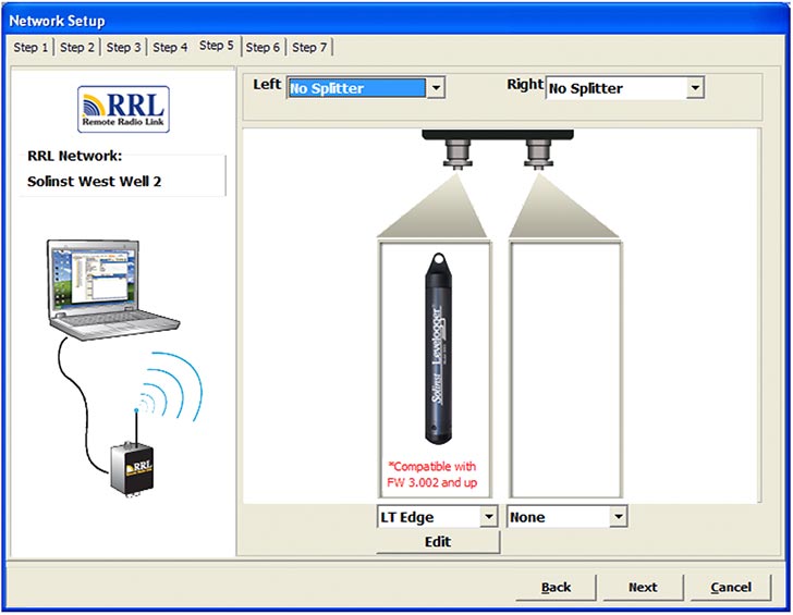
In this step you will select the number and types of water level dataloggers connected to the RRL Station.
The connectors for dataloggers on the RRL Stations are identified as Right and Left. This assumes the RRL Station is facing with the black label towards you. If using a Splitter, the number 1 or 2 will identify the dataloggers. The numbers 1 and 2 are labeled directly on the connections of each Splitter.
For each connection you will select the type of datalogger attached. Select 'NONE' for connectors with no datalogger attached. After selecting the datalogger type from the drop down menu, an image of the selected datalogger will be displayed.
Note:
The firmware versions shown in red for each datalogger, are the firmware versions that will work with the current Solinst Telemetry Software version.
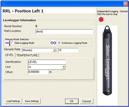
To optionally set each datalogger to record in their internal memory, select Edit to begin entering data collection information.
Note:
Dataloggers programmed to record and store readings in their internal, non-volatile memory, provide reliable back-up data. This will, however, cause their internal battery to be used up more quickly.
You must program a Rainlogger in order to enter a Rainfall Calibration Constant (the amount of rainfall per tip of the connected rain gauge), but you do not have to set it to record independently.
Select Next, without editing any datalogger settings, if you do not want to set your dataloggers to record independently.

Figure 4-8 Adding Dataloggers

Figure 4-9 Datalogger Information Window


