- Start the WLTS Utility.
- Select the appropriate Com Port for the connected WLTS from the drop-down menu.
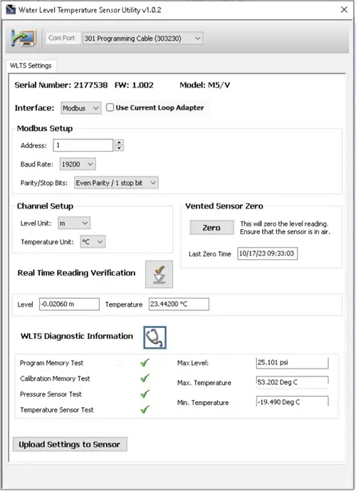
- Click the 'Retrieve Settings' icon. This will retrieve and display the current programmed settings for the connected WLTS, as well as the serial number, firmware version, and model.
- You can now customize the WLTS protocol and measurement parameter settings. Select MODBUS or SDI-12 from the Interface drop-down.
- MODBUS settings options include: Address (set between 1 and 247), Baud Rate, Parity and Stop Bits.
SDI-12 settings include the Address (The address can be customized to any value from "0" to "9", "A" to "Z", or "a" to "z", giving a total of 62 unique addresses).
Note:
Without setting a specific address or Baud rate, the WLTS will power up with a default MODBUS device address of 1, Baud rate of 19,200, even parity and 1 stop bit).
- For both protocols, set the units that the WLTS will be measuring in for the Level and Temperature Channels. When finished, click Upload Settings To Sensor.
- To test that the Sensor is reading correctly before connecting it to the Communication/ Vented Cable for deployment, you can click the Real Time Reading Verification icon to obtain real-time readings from the Sensor.
- If further Diagnostic Information is required, click the Diagnostics icon to perform a series of tests (Memory and Sensor) and obtain Level and Temperature information that may be helpful when troubleshooting any issues.
![]()
Note:
Without setting a specific address, the WLTS will power up with a default SDI-12 device address of 0. The communication settings for the WLTS comply with the SDI-12 standard at 1200 baud, 1 start bit, 7 data bits, 1 parity bit (even parity), and 1 stop bit.
Note:
You can also perform a "Field Zero" in air for the vented sensors.
Note:
See the 301 WLTS User Guide for your specific communication protocol (MODBUS, SDI-12) for full definitions of the available commands.

Water Level Temperature Sensor WLTS PC Software Utility - Diagnostic Information
![]()
![]()


