To activate the modem, you will require a dynamic IP Address supplied by the service carrier to be assigned to the modem. They will also provide you with an activated SIM card and an APN (Access Point Name).
Note:
Refer to the online instructions to complete the physical set up of the modem, including antenna connection and SIM card installation: www.DIGI.COM/IX20/START
The following are the steps required to set up the modem:
- Attach the antennas to the modem.
- Insert your SIM card into the top (SIM 1) spot of the modem, contacts facing down (see illustration).
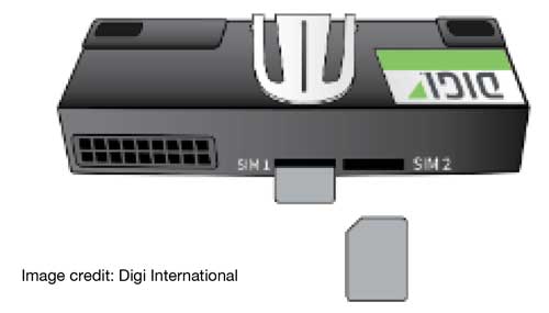
Figure 3-7 Inserting SIM Card
Note:
There are two SIM card slots in the modem. Install the SIM card in the left slot, with the chamfered corner inserted first. The contacts should be face down.
- To turn the modem on, you will need to use the STS Field Utility. The modem will need to be connected to the STS using the Modem Power Cable, the 12V battery connected to the STS, and the STS connected to the PC using the USB Programming Cable. See Section 4.8.1 for instructions to turn on the modem using the STS Field Utility.
- When the modem is powered-up, the LEDs illuminate and a series of diagnostic self-tests is initiated. When the flashing stops, the self-test diagnostic is complete and the modem is ready to be configured.
- Turn the WiFi off on your PC. Connect the Ethernet cable from the ETH2 port on the modem to a LAN port on your PC. IP should be set to Automatic (the modem sets the IP of the PC).
- Open your web browser and enter the IP Address "192.168.2.1" in the URL address bar. The 'Getting Started Wizard' for the modem will open.
- Enter the default Username: Admin, and the Password for the modem that is on the label on the bottom of the modem, or a sticker affixed to the inside of the STS NEMA enclosure.
- The main Dashboard provides a summary of the current configuration.
- Go to "Network Interfaces" then "Modem". Enable "APN list only". Add the APN of your SIM card to the list, then click Apply. The APN will be provided by your service carrier. The APN for Solinst SIM cards is globaldata.net.
If the modem firmware is not version 21.5 or higher (this can be found on the Dashboard) then it must be updated from the Digi website, and then the APN set up repeated.
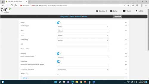
Figure 3-9 Modem Settings
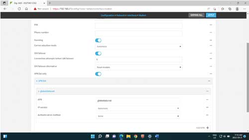
Figure 3-10 APN Setting
- Steps 11-13 are needed if the STS will be connected to the modem via a Serial (RS 232) cable. If using an Ethernet connection (for Bridging) from the STS to the modem, then the settings will automatically be applied.
- From the Dashboard, go to "System" then "Serial Configuration".
- Enable "Port 1".
- Scroll down to "Serial Settings" . The following settings should be entered and Applied:
- Baud Rate: 115200 bits/second
- Data Bits: 8
- Parity: None
- Stop Bits: 1
- Flow Control: None
- Scroll down to "Autoconnect Settings" and enable.
- Set Connection Trigger to "Data received from the serial port", the Outbound Connection Type to "Raw TCP Connection", and set the Destination (Static IP) and IP Port number to the public IP of the PC running the STS home station Communication Agent. Click Apply to save the settings.
If the modem set up is successful, it is recommended to power cycle the modem, test the new password, and possibly test Internet access.
Note:
It is recommended to set the TCP Port to 49200.
Note:
Internet access will only work after restoring the default gateway IP of the PC, if it was modified.
- Disconnect the PC, and connect the STS to the Serial port or ETH2 of the modem.
- Use STS Field Utility to set up the STS through the USB port. Set the desired communication mode along with the related parameters. For Serial (RS 232) mode, use settings that match what the modem was set to. For Ethernet mode or Bridging mode, use the port number as selected in the STS Administrator Software, and with the Public IP address of the PC on which the Communication Agent will be running.
- Power up the modem and wait for connection, then do a Home Station communication test via the Field Utility. If that fails, try power cycling the STS (which also powers the modem), and try again after they boot up (4 minutes).
Note:
To avoid extra cellular data charges caused by connected PC data transmission through the modem over the Internet during setup, do the following: The default subnet of the modem is 192.168.2.0/24, and its default configuration page is 192,168.2.1. So set the PC to manual IP mode, and set its default gateway so that it points AWAY from 192,168.2.1.
Note:
If there is trouble logging in, push the (hidden) ERASE button on the modem with a paper clip to restore the default password. Enter a new password for the administrator and click Apply.
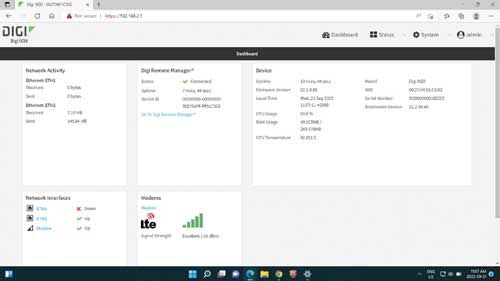
Figure 3-8 Main dashboard
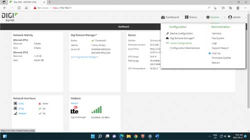
Figure 3-11 Serial Configuration
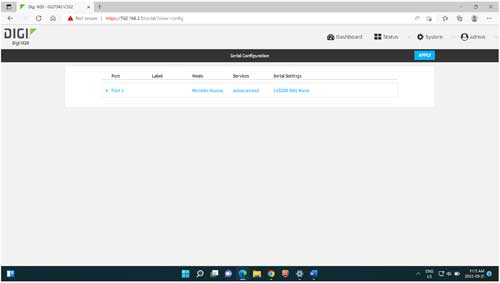
Figure 3-12 Serial Port Configuration
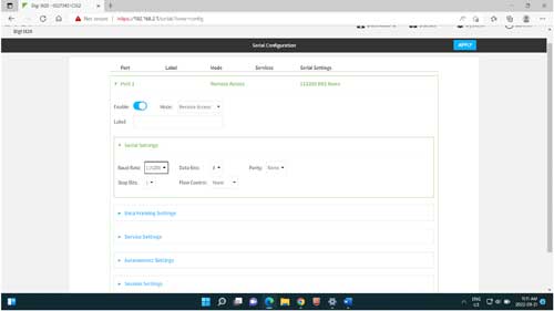
Figure 3-13 Serial Settings
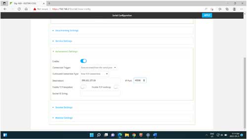
Figure 3-14 Autoconnect Settings


