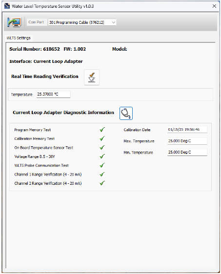
The WLTS PC Software Utility can be used to perform diagnostics on the WLTS Current Loop Adaptor.
To communicate with the WLTS Current Loop Adaptor, the switch must be in the SW=3 (third) position. The modes should only be switched when there is no power applied to the WLTS Current Loop Adaptor.
See Section 2.1 for proper connection of the USB-A Programming Cable to the connection on the WLTS Current Loop Adaptor circuit board.
Plug the USB-A Programming Cable into your computer. Upon power-up, the WLTS Current Loop Adaptor performs a self-test while the tri-color LED blinks blue, red, and stays on at green.
Start the WLTS Software Utility. Select the appropriate Com Port for the connected WLTS Current Loop Adaptor from the drop-down menu.
Click the 'Retrieve Settings' icon  . This will retrieve and display the information for the connected WLTS Current Loop Adaptor, including the serial number and firmware version.
To test that the Sensor is reading correctly, you can click the 'Real Time Reading Verification' icon ![]() to obtain real-time readings.
to obtain real-time readings.
Click the 'WLTS Diagnostics Information' icon ![]() to perform a series of tests to obtain information that may be helpful when troubleshooting any issues. Take a screenshot of this information to share for troubleshooting support.
to perform a series of tests to obtain information that may be helpful when troubleshooting any issues. Take a screenshot of this information to share for troubleshooting support.

Figure 2-6 WLTS Current Loop Adaptor Diagnostic Information


