Note:
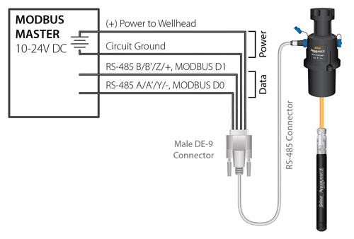
Solinst only supplies the Connector Cables which connect to the Solinst AquaVent SPX Wellhead. The customer must supply all wiring to connect to the MODBUS equipment, and must ensure correct pin-to-pin connection with the Connector Cables according to the pin-out diagrams provided.

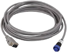
Figure 3-6 Solinst AquaVent RS-485 Modbus Connector Cable
Two-wire MODBUS over RS-485 Connector Cable is equipped with a male DE-9 connector. The other end of the Connector Cable connects to the 12-Pin connection on the SPX Wellhead.

Shell: Cable Shield Drain
1: Circuit Ground
2: (+) Power to Wellhead
3: N.C.
4: N.C.
5: RS-485 B/B'/Z/+, MODBUS D1
6: N.C.
7: N.C.
8: N.C.
9: RS-485 A/A'/Y/-, MODBUS D0
Figure 3-7 RS-485 Male DE-9 Connector (front view)
Note:
The AquaVent uses 2-wire Modbus. for 4-wire equipment, connect customer wires as labelled.

Figure 3-8 RS-485 Wiring Overview


