Note:
Solinst only supplies the Connector Cables which connect to the SPX Wellhead. The customer must supply all wiring to connect to the MODBUS equipment, and must ensure correct pin-to-pin connection with the Connector Cables according to the pin-out diagrams provided.

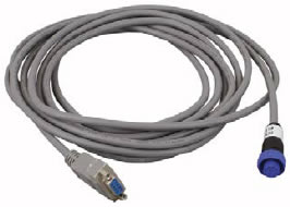
Figure 3-3 RS-232 Connector Cable
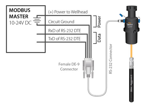
Refer to the wiring diagrams below for correct connection of the RS-232 and RS-484 Connector Cables to the MODBUS master, including external power to the Wellhead (10 - 24V).
3.2.1 RS-232 Connection
The MODBUS over RS-232 Connector Cable is equipped with a female DE-9 connector. The other end of the Connector Cable connects to the 12-Pin connection on the Solinst AquaVent SPX Wellhead.

Shell: Cable Shield Drain
1: N.C.
2: RxD of RS-232 DTE Industry Standard
3: TxD of RS-232 DTE Industry Standard
4: N.C.
5: Circuit Ground Industry Standard
6: N.C.
7: N.C.
8: N.C.
9: (+) Power to Wellhead (Note: This pin would normally be RI (Ring Indicator)
Figure 3-4 RS-232 Female DE-9 Connector (front view)
Note:
Solinst recommends that the RI signal of the customer equipment NOT be connected.

Figure 3-5 RS-232 Wiring Overview


