Tools and Materials Needed

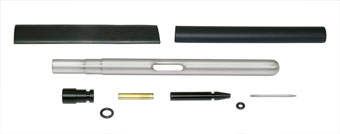
P2 SS Probe with Seal Kit (#102979)
- P2 SS Probe with Seal Kit (#102979)
- Wire Cutters
- Wire Stripper
- Jig or Clamps (optional)
- Heat Gun
Instructions
Instructions to attach a new P2 Probe (part #102979) to a Solinst Model 101 Water Level Meter, ensuring accurate depth to water level measurements. The new P2 Probe assembly is carefully and properly sealed to the tape using heat shrink and a heat gun.
Note:
These instructions refer to a tape with 1/10 ft markings NOT inches. Metric conversions are provided in brackets.
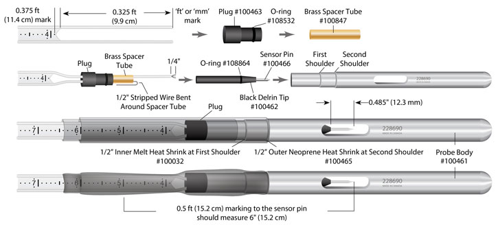
- Cut tape at point zero ("ft" or "mm" mark). Cut along the lead wires from point zero to the 0.325 ft (9.9 cm) mark on the tape. Cut in a triangle formation pointing to the 0.375 ft (11.4 cm) mark.
- Thread the two wires from the flat tape through the plug.
- Thread both wires into the brass spacer tube.
- Cut one wire 1/2" (1.2 cm) longer than the brass spacer tube, as shown in the diagram. Strip that wire from the end of the brass spacer tube. Bend the stripped wire over the brass spacer tube.
- Place the end of the black delrin tip against the end of the brass spacer tube. Measure the other wire to extend just past the o-ring on the black delrin tip and cut. Strip approximately 1/4" (6 mm) of this wire, and twist the wire loose. Twist the black delrin tip onto this wire, down to the brass spacer tube.
- Insert the wedge end of the sensor pin into the tapered end of the black delrin tip. To ensure the sensor pin is positioned at the correct zero point, push the sensor pin into the black delrin tip until, when measured, the distance between the 0.5 ft (15.2 cm) marking on the tape and the sensor pin is 6" (15.2 cm). The shoulder of the black delrin tip to the end of the sensor pin should measure 0.485" (12.3 mm), to ensure correct measurements.
- As you push the inner components into the probe body twist the probe gently to fit over the o-rings (some vaseline on the o-rings helps ease the probe on).
- Slip the inner melt heat shrink (round heat shrink) over the probe onto the flat tape, and against the first shoulder on the probe body. Apply heat starting from the center working outward, pressing the heat shrink on tape with fingers to smooth out.
- Slip the outer neoprene heat shrink (flat heat shrink) over the inner melt heat shrink against the second shoulder on the probe body. Apply heat starting from the center working outward. Press the heat shrink onto the tape with your fingers.
Note:
The sensor pin must be positioned correctly to give accurate measurements. It will take some force to get the sensor pin positioned correctly, a jig or clamps may help.
Note:
Be careful not to melt the tape with the heat gun.


