Note:
To replace the light in an Mk1 Water Level Meter (yellow circuit board and tape Molex connection), you will require the Mk2 Circuit Board Assembly (#102977), which includes the light. Contact Solinst for the repair part and instructions.
Tools and Materials Needed

- WLM Replacement LED (Light) Assembly (Spare) (#113923)
- Phillips Screwdriver
- 10 mm (3/8") Wrench
- Wire Cutters (if required)
- Wire Strippers (if required)
- Solder Wire with Flux
- Soldering Iron
Instructions
For Mk2 Water Level Meters (Push-Release Tape Connection)
- Remove the battery (battery is located inside the reel hub of a 102M Mini Water Level Meter. Remove the batttery after Step 2).
- Unscrew the three screws and remove the faceplate.
- Press down on the white terminals of the push-release fittings on the circuit board and pull out to remove the tape leads.
- If you have an older style light (leads connected to Sonalert terminals – see photo below), cut the red and black wires connected to the light, and push the light out through the front of the faceplate.

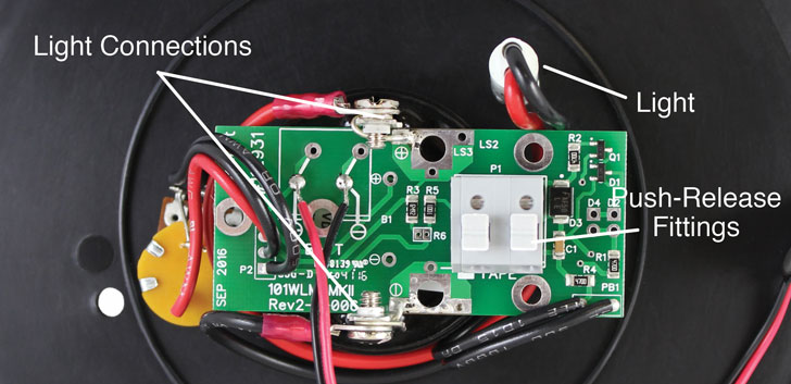
Back of Mk2 Water Level Meter Faceplate with Older Style Light
Back of Mk2 Model 102M Mini Water Level Meter Faceplate with Older Style Light

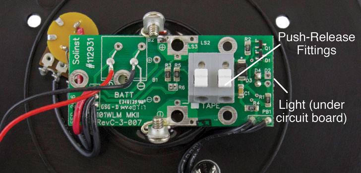
Back of Mk2 Water Level Meter Faceplate with New Style Light
Back of Mk2 Model 102M Mini Water Level Meter Faceplate with New Style Light
- From the front of the faceplate, use the wrench to unscrew the nut holding the test button and push the button back out of the faceplate.
- Unscrew and remove the two screws holding the circuit board (and older style light leads) from the Sonalert.
- Carefully lift the circuit board from the Sonalert so you have better access to the circuit board.
- If you have a newer style light, unsolder it from the circuit board and remove as much of the old solder as possible.
- If you had an older style light (or the lens needs replacing) insert the new red lens through the opening in the faceplate and secure using the white nut.
- For a Model 101 or 102 Water Level Meter, insert the leads of the new light into the two positions labelled "D2" on the circuit board and solder in place. See photo below.


- For a Model 102M Mini Water Level Meter, insert the leads of the new light into the two positions labelled "D4" on the circuit board and solder in place ("D4" positions are located next to "D2" positions). See photo above.
- Place the circuit board assembly back into position on top of the Sonalert, ensuring the sides marked +ve and -ve are lined up with the corresponding terminals on the Sonalert and the new light seated in the lens.
- Reinstall the two screws to connect the bare wires from the circuit board to the terminals on the Sonalert.
- Insert the test button through the opening in the faceplate, and secure it in place using the nut.

- For 101 Water Level Meters, connect the tape to the circuit board assembly by pressing down on the white terminals on the circuit board and inserting the tape leads. Release the terminals and the leads should be secured. The lead on the top of the tape (numbers facing up, or see note) is inserted into the terminal with a white square below it on the circuit board.
- For 102 and 102M Water Level Meters, connect the cable to the circuit board assembly by pressing down on the white terminals on the circuit board and inserting the leads. Release the terminals and the leads should be secured. The negative lead is inserted into the terminal with white square below it on the circuit board. The negative pin is connected to the black insulated braided wire, the positive lead has the pin connected to centre wire.
- Install the battery.
- With the probe in a glass of tap water, turn the Water Level Meter to the 'ON' position. If the connections are correct the light will activate. If the light does not activate, check all connections and the polarity of the battery.
- Reattach the faceplate to the reel using the three screws.
Note:
There is a "P" etched on the tape to help denote the proper orientation of the tape – top and bottom leads.