Tools and Materials Needed
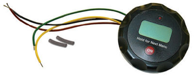
- 107 TLC Replacement Display Assembly (#110647)
- Phillips or Robertson Screwdriver
- Socket Screwdriver (or 10-32 Hex Key)
- Wire Cutters
- External C-Ring Pliers
- Solder Iron and Wire
- Heat Gun

TLC Replacement Display Assembly (#110647)
Instructions
- Turn OFF the TLC Meter and remove the 9V battery.
- Unscrew the three screws on Faceplate and slowly remove the Faceplate from the Reel.
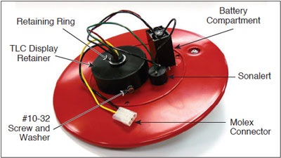
- Disconnect the white Molex connector inside the Reel Hub.
- Cut the cable tie wrapped around the wires.

- Using the socket screwdriver, unscrew the #10-32 screw and washer from the Display Retainer on the back of the Faceplate.
- Cut the yellow and black wires connected to the white Molex connector, about 2" (50 mm) from the edge of the connector. You will need the Molex connector for re-attachment.
- Unsolder the green wire from the Sonalert, and unsolder the red and black wires from the Battery Compartment.
Note:
The shorter black wire connected to the Sonalert is also connected to the Battery Compartment. It may come off during unsoldering. The wire will be resoldered in Step 13.
- Remove the washer and retaining ring using the external C-ring pliers.
- Push the TLC Display Assembly through the front of the Faceplate and remove.
- From the front of the Faceplate, feed the four wires of the new TLC Display Assembly through the opening in the Display Retainer. Position the Assembly in the Display Retainer until the Display Base (rotating part of TLC Display Assembly) becomes flush with the front of the Faceplate.
- Refasten the #10-32 screw and washer to the Display Retainer.
- Position and refasten the washer and retaining ring using the external ‘C’ ring pliers.
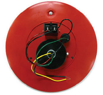
- Solder the wires from the new TLC Display Assembly as shown in the photo below. Solder the green wire to the positive terminal on the Sonalert; solder the red wire to the positive terminal on the Battery Compartment; solder the black wire from the new TLC Display Assembly, together with the shorter black wire from the Sonalert, to the negative terminal on the Battery Compartment.>

Back of TLC Faceplate Showing Wiring Connections
- Strip about 1/4" (6 mm) of the insulation from the longer black wire connected to the Sonalert, and the yellow wire from the new TLC Display Assembly. Also strip the yellow and black wires still connected to the Molex connector.
- Slide the piece of heat shrink over the yellow wire from the Display Assembly and black wire from the Sonalert, and push out of the way.
- Twist the stripped yellow wire of the Molex connector together with the yellow wire of the Display Assembly, and the black wire of the Molex connector with the black Sonalert wire. Solder the twisted connections.
- Slide the heat shrink over the soldered connections and apply heat using the heat gun. Press the heat shrink onto the connection with your fingers.
- Tie all the wires together with the cable tie.
- Connect the Molex connector inside the Reel Hub.
- Replace the battery in the TLC Meter.
- With the Probe in a glass of tap water, turn the TLC Meter ‘ON’. If the buzzer or light do not activate, or the LCD does not show temperature or conductivity, check the soldered and Molex connections.
- Replace the Faceplate and fasten the three screws.


