Tools and Materials Needed
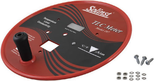
- 107 Mk3 SC1000 Faceplate w/o Electronics (#113482)
- Phillips or Robertson Screwdriver
- Small Flat Screwdriver
- Needle Nose Pliers
- Small Sharp Knife
- Any Available Plastic Adhesive/ Sealant (e.g. silicone)

Instructions
- Place the reel on a flat workbench with the faceplate up. Make sure the TLC Meter is turned off. Remove the battery.
- Undo the three screws from the faceplate, and slowly remove it from the reel.
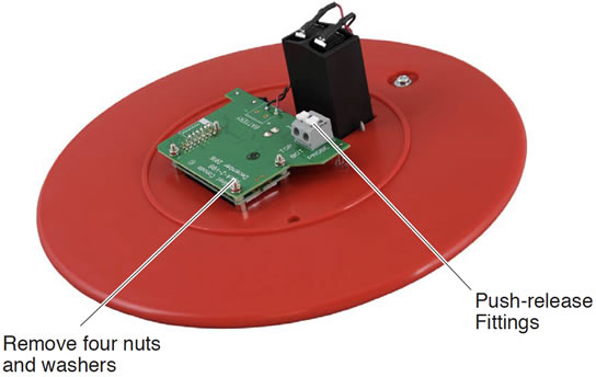
- Press down on the white terminals of the push-release fittings on the circuit board and pull out to remove the tape leads.

Back of the Solinst Model 107 Mk3 TLC Meter Faceplate
- Pull to remove the two leads from the terminals on the battery tray.
- Undo the two screws holding the battery compartment and remove it from the faceplate. Do not lose the screws.
- Use the pliers to unscrew the nut holding the push button on the front of the faceplate. Do not lose the nut.
- Use the pliers to remove the four nuts and washers holding the circuit board to the support posts on the faceplate.
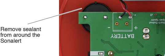
- Use a small sharp knife to remove the sealant from around the Sonalert and light.

- Pull straight up to remove the circuit board and display assembly from the faceplate. Be careful when pulling to ensure the Sonalert and light are removed safely and remain connected to the circuit board.
- Install the battery tray through the front of the new faceplate, and secure using the two screws.
- Apply a small amount of sealant around the edge of the Sonalert to hold it in place against the back of the faceplate.
- Ensure there are four washers installed, and place the circuit board and display assembly into position over the four support posts on the back of the new faceplate. Ensure the push button and light are positioned correctly.
- Use four washers and nuts to secure the circuit board and display assembly to the support posts on the new faceplate.
- Use the nut to secure the push button to the front of the faceplate.
- Connect the black wire lead from the circuit board assembly to the negative terminal on the battery tray. Connect the red wire lead to the positive terminal.
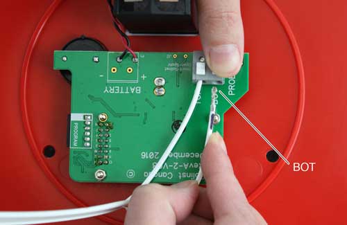
- Press down on the white terminals on the circuit board and insert the tape leads. Release the terminals and the leads should be secured. The lead on the bottom of the tape (see note) is inserted into the terminal labelled BOT on the circuit board, and the top lead into the terminal labelled TOP.
Note:
There is a "P" etched on the tape to help denote the proper orientation of the tape – top and bottom leads.


- Replace the battery in the TLC Meter.
- With the Probe in a glass of tap water, turn the TLC Meter 'ON'. If the buzzer or light do not activate, or the LCD does not show temperature or conductivity, check the connections.
- Secure the new faceplate to the reel with the three screws.


