122M Mini Interface Meter: Operating Principles


Operating Principle
The Solinst Model 122M Mini Interface Meter has a narrow 5/8" (16 mm) diameter probe, and uses laser-marked PVDF jacketed cable. It is certified to CSA Standards, for use in hazardous locations Class 1, Div. 1, Groups C & D T3C, and is ATEX certified under directive 94/9/EC, as II 3 G Ex ic IIB T4 Gc. An infra-red circuit detects the presence of a liquid and a conductivity circuit differentiates between conductive liquid (water) and non-conductive liquid (LNAPL or DNAPL product).
Equipment Check
Check the electronics and battery condition by pushing the ‘On/OFF’ button. Five brief tones and red light flashing indicates that the meter is functional. It will automatically turn off after 5 minutes to preserve battery life.
Important:
For safety, always ground the meter by attaching the ground cable to the metal well casing or to a suitable grounding rod. Failure to properly ground this instrument could cause damage to probe/electronics or result in an explosion from any flammable gases trapped in well.
Field Measurements
- Push the ‘On/OFF’ button. Five brief tones and the red light flashing indicates that the meter is functional. The meter automatically turns off after 5 minutes. Press the ‘On/OFF’ button as necessary during operation to turn the meter back on.
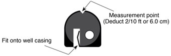
- Lower probe into well. If a tape guide is used, lay the laser-marked PVDF cable onto the groove on the top. Measurements are read at the V-notch on the tape guide. Remember to deduct 2/10 ft or 6.0 cm.
- A steady tone and light indicate a non-conductive liquid (e.g. product). An intermittent tone and light indicate a conductive liquid (e.g. water).
- For floating product (LNAPL), take the air/product interface measurement on the way into the liquid.
- The interface between the LNAPL and water should be measured as the probe is raised very slowly back up. Once the interface is detected, the probe can be raised and lowered in small increments to precisely determine the interface.
- Repeat measurements to confirm, reading the levels directly from the cable and subtract one from the other to determine thickness.
- To determine if there is any sinking product (DNAPL) in the well, continue lowering the probe slowly. If steady signals activate, determine the top of the sinking layer by reading directly from the cable.
- Continue lowering the probe slowly until the cable slackens when the well bottom is reached. Read the level directly from the laser-marked PVDF cable and subtract one from the other to determine thickness.
- Upon completion of readings, clean the cable and probe as described overleaf.
Tape Guide