Tools and Materials Needed
- Tape/Cable to Reel Connector Set for Water Level Meter
Devices (Spare) (#103413), includes:
- 3 x Molex Pin Contacts (male)
- 3 x Molex Pin Socket Contacts (female)
- 3 Pin Molex Plug Connector
- 3 Pin Molex Socket Connector
- 1/8" x 1" Black Inner Melt Heat Shrink (for Model 102/122M P8 only)
- #2 Phillips or Robertson Screwdriver
- Wire Cutters
- Wire Strippers
- Molex Pin Crimping Tool or Suitable Pliers
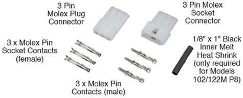
Tape/Cable to Reel Connector Set for Water Level Meter Devices (Spare) (#103413)
Tape Molex Connector Instructions
- Place reel on a flat workbench with faceplate up and remove the battery.
- Undo the three screws from the faceplate, and slowly remove it from the reel.
- Disconnect the Molex connector on the tape from the Molex connector from the faceplate.
- Use the wire cutters to cut each wire connected to the Molex plug connector and the Molex socket connector. Cut the wires as close to the connectors as possible.
Note:
This includes cutting the ground wires of a Model 122.
- Strip each of the cut wires by about 1/4" (6.4 mm).
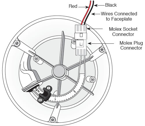
Model 101 P7 (See Note for 101 P2)
Note:
The original Molex connectors being removed from a 101 P2 may be 2 pin, and the Molex socket and plug connectors will be opposite of the 101 P7 and 107 connectors. One terminal in the new 3 pin Molex connectors will be left unused, as with the 101 P7 and 107.
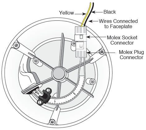
Model 107
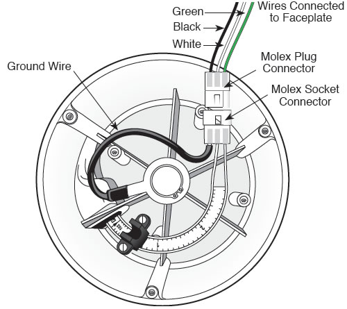
Model 122 P8
- Use the Molex pin crimping tool or pliers to connect the appropriate pin to each wire. Then, by hand, insert each pin into the appropriate Molex connector. Ensure pins are pushed as far as possible into the connectors. Each Model will have different pin and Molex connector arrangements, please refer to the illustrations and photos below for your specific Model:
Note:
The Model 101 P2, 101 P7 and 107 will only use two sets of Molex Pin Contacts. The Model 122 and 122M use all three sets.
Important:
In all cases, the negative wire, which is on the top of the tape (with numbers facing up) is inserted into the terminal on the pointed side of the Molex plug or socket connector.

Model 101 P2:

Model 101 P7:

Model 107:

Model 122 P8:

- Connect the Molex plug connector on the tape to the Molex socket connector from the faceplate. Replace the battery.
- With the Probe in a glass of tap water, turn the Water Level Meter/TLC/Interface Meter ‘ON’. If the buzzer or light do not activate, check the connections. With the Model 107 TLC, make sure the display on the faceplate is working. Also test the 122 P8 and 122M P1 in product, as well as the water.
- Replace the faceplate on the reel and re-secure the three screws.
Tools and Materials Needed
- Tape/Cable to Reel Connector Set for Water Level Meter Devices (Spare) (#103413), includes:
- 3 x Molex Pin Contacts (male)
- 3 x Molex Pin Socket Contacts (female)
- 3 Pin Molex Plug Connector
- 3 Pin Molex Socket Connector
- 1/8" x 1" Black Inner Melt Heat Shrink
- #2 Phillips or Robertson Screwdriver
- Wire Cutters
- Wire Strippers
- Molex Pin Crimping Tool or Suitable Pliers
- Heat Gun
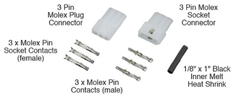
Tape/Cable to Reel Connector Set for Water Level Meter Devices (Spare) (#103413)
Cable Molex Connector Instructions
- Place the reel on a flat workbench with the faceplate up and remove the battery. Undo the three screws from the faceplate, and slowly remove it from the reel.
- Disconnect the Molex connector on the cable from the Molex connector from the faceplate.
- Use the wire cutters to cut the old Molex connector from the cable. Cut off where the heat shrink ends on the cable (see below). Cut off the wires from the faceplate electronics connected to the Molex connector. Cut the wires as close to the connector as possible.
- Strip the wires from the faceplate by about 1/4" (6.4 mm).
Note:
This includes cutting the ground wires of the Model 122M P8.
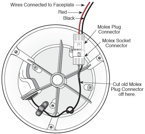
Model 102 / 102M
Note:
The original Molex connectors being removed from a Model 102 or 102M may be 2 Pin. The third terminal in the new 3 pin Molex connectors will be unused.
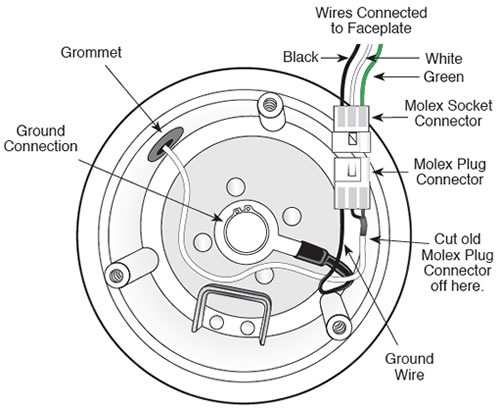
Model 122M P8
- Use the Molex pin crimping tool or pliers to connect the appropriate pin to the wires from the faceplate. Then, by hand, insert each pin into the appropriate Molex connector. Ensure pins are pushed as far as possible into the connector. Refer to the illustrations and photos below and overleaf for your specific Model:
Note:
The Model 102 and 102M will only use two sets of Molex Pins. The Model 122M P8 will use all three sets.
Model 102/102M:
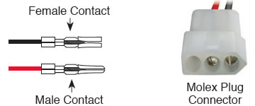
Model 122M P8:
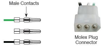
- Slide the piece of heat shrink onto the cable, and push out of the way.
- Strip 1-1/4" (32 mm) off the cable’s outer jacket exposing the braided wire.
- Undo the braided wire and divide the strands into two equal groups. Twist the wire strands of one of the groups together. Remove the other group by cutting the strands at the edge of the outer coating.
- Strip the inner insulation of the cable approximately 1/4" (6.4 mm) exposing the stainless steel wire.

Note:
The Model 122M P8 will have a white outer jacket.
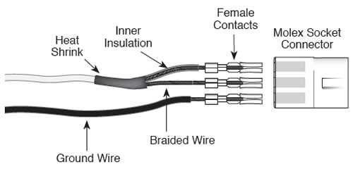
- Use the Molex pin crimping tool or pliers to connect the appropriate pin to each wire. By hand, insert the pins into the new Molex connector. Ensure the pins are pushed as far as possible into the connector. Refer to the illustrations below and above right for your specific Model:
Model 102/102M:
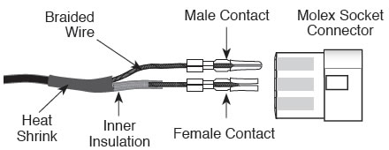
Model 122M P8:
- Slide the piece of heat shrink up to cover the point where the outer coating was stripped away and half the strands of braided wire were removed.
- Using the heat gun, carefully apply heat from the centre working outward to prevent air pockets forming under the heat shrink.
- Connect the Molex plug connector on the tape to the Molex socket connector from the faceplate. Replace the battery.
- With Probe in a glass of tap water, turn the Water Level Meter/Interface Meter to the ‘ON’ position. If the buzzer or light do not activate, check the connections. Also test the 122M P8 Interface Meter in product, as well as the water.
- Replace the faceplate and re-secure the three screws.


