Tools and Materials Needed
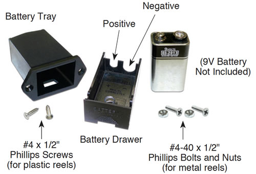
- Replacement Battery Drawer Assembly (#103559), includes:
- Single 9 Volt Battery Tray/Drawer (#103308)
- 2 x #4 x 1/2" Phillips Screws (#101712) for plastic reels
- 2 x #4-40 x 1/2" Phillips Bolts (#100103)
and 2 x #4-40 Nuts #102154) for metal reels
- Phillips Screwdriver
- #4-40 Wrench (for metal reels)
- Wire Cutters and Strippers (if required)
- Soldering Wire and Iron (if required)

Instructions
- Remove the battery drawer from the faceplate.
- Undo the three screws from the front of the faceplate and remove the faceplate from the reel.
- For Meters with a Molex connection, undo the connector that connects the faceplate electronics to the tape.
- For Meters with the tape leads connected to the circuit board, press down on the white terminals of the pushrelease fittings and pull to remove the tape/cable leads. Note how they are connected.
- For the Meters with a Molex connection, cut the red and black wires from the back of the battery tray close to the terminals.
- For the Meters where tape leads were connected to the circuit board, simply pull to remove the red and black wires from the terminals on the battery tray.
- Undo the two screws (and nuts for metal reels) holding the battery tray in the faceplate. Remove the old battery tray.
- Place the new battery tray through the faceplate and secure it with the two screws (and nuts where required).
- For the Meters with a Molex connection, strip the red and black wires, cut from the old battery tray, about 1/4" (6 mm). Solder the black wire(s) to the negative terminal on the battery tray, and the red wire to the positive terminal. The terminals are labeled on the tray.
- For the Meters where tape leads were connected to the circuit board use the quick-connect fittings on the red and black wires to connect the black wire to the negative terminal on the battery tray, and the red wire to the positive terminal. The terminals are labeled on the tray.
- Note the polarity and place the battery in the new battery drawer. The positive terminal of the battery is placed towards the small notch in the end of the drawer.
- Slide the battery drawer into the battery tray in the faceplate.
- If applicable, reconnect the Molex connector from the faceplate electronics to the tape.
- If applicable, press down on the white terminals on the circuit board and insert the tape/cable leads. Release the terminals and the leads should be secured.
For the Mk3 107 and 201, the lead on the top of the tape is inserted into the terminal labelled TOP on the circuit board.
For the Mk2 101, 101D, and 105, the lead on the top of the tape (top of numbers or see note below) is inserted into the terminal with a white square below it on the circuit board.Note:
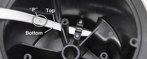
There is a "P" etched on the tape to help denote the proper orientation of the tape – top and bottom leads.

For the Model Mk2 102, the negative lead is inserted into the terminal with a white square below it on the circuit board. The negative pin is connected to the black insulated braided wire.
- Test that the Meter is working correctly. Refer to the Operating Instructions, if required.
- Use the three screws to replace the faceplate back on the reel.
Note:
To remove the battery drawer, press the drawer in, lift then pull. The battery drawer should slide out of the faceplate enough to pull it out and remove.
Note:
Model 122 P8 Interface Meters have two black wires connected to the battery tray.
Note:
For Model 122 P8 Interface Meters, solder the black wire with brown resistor, to the positive terminal on the battery tray.


