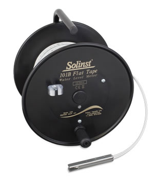
Tools and Materials Needed
- Model 101B Replacement PCB Assembly (#112172)
- 2 x #4-40 x 1/2" Phillips Flat Head Cap Screws
- 2 x #4-40 x 1/4" Phillips Pan Head Screws
- Large Phillips or Robertson Screwdriver
- Small Phillips Screwdriver
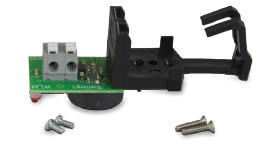
101B Water Level Meter Replacement PCB Assembly

Instructions
- Place the reel on a flat workbench with the faceplate up. Undo the three screws from the faceplate, including the screw from the probe holder, and slowly remove the faceplate from the reel.
- Remove the battery from the PCB assembly.
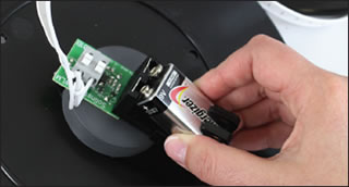
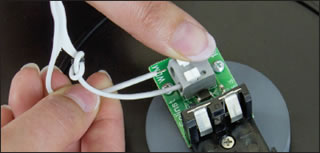
- Press down on the white terminals, and pull out to remove the tape leads from the PCB assembly.
- Use the small Phillips screwdriver to undo the four screws holding the PCB assembly to the old faceplate. Remove the PCB assembly.
If there are white nylon spacers around each of the four screws, save them to reuse in the next step.
- Attach the new PCB assembly to the back of the faceplate using the four screws. Ensure the light on the assembly is positioned correctly in the lens.
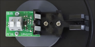
- Push down on the white terminals and insert the tape leads into the new PCB assembly. Release the terminals and the tape leads should be secured.
It does not matter which lead goes into which terminal.
- Install the battery in the new PCB assembly.
- Dip the probe in a glass of tap water. If the connections are correct, the buzzer and light on the Meter will be activated. Check connections if the buzzer and light do not activate.
- Attach the faceplate to the reel using the three screws. Remember to replace the probe holder using the top left screw.


