Connecting Laser Marked Replacement Tape to Reel
Depth Discrete Groundwater Monitoring
Reduce Costs and Field Time
Tools and Materials Needed
- Replacement Laser Marked Tape Assembly, Includes:
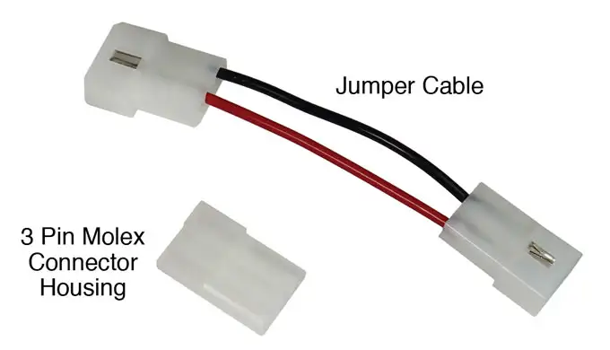
- Jumper Cable (New Tape – 3 Pin to 2 Pin) (#110508)
- 3 Pin Molex Connector Housing
- Grommet
- Phillips or Robertson Screwdriver
- Wire Cutters
- Pliers (if required)
Note:
The Jumper Cable is only required if you are connecting the new Laser Tape to a Mk1 Model 101 Water Level Meter that previously used polyethylene tape (with red ft/m markings). The Molex Connector from the faceplate electronics will have a 2 pin connection.
Instructions
- Place the reel on a flat workbench with the faceplate up. Undo the three screws from the faceplate, and slowly remove it from the reel.
- For Meters with a Molex connection, disconnect the old Tape Molex Connector from the Faceplate Molex Connector.
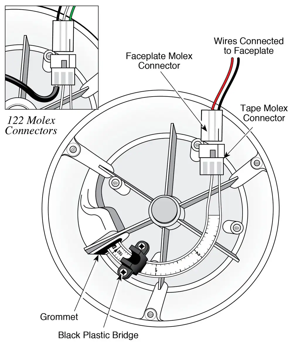
Inside View of Mk2 107/Mk1 101 P7 Reel Hub
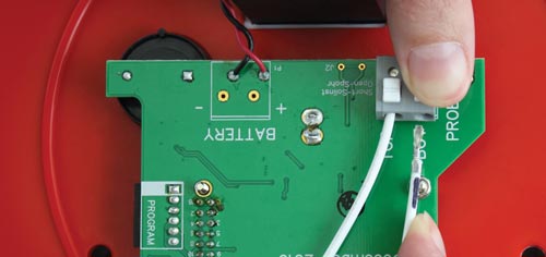
3. For Meters with the tape leads connected to the circuit board, press down on the white terminals of the push-release fittings to remove the tape leads.
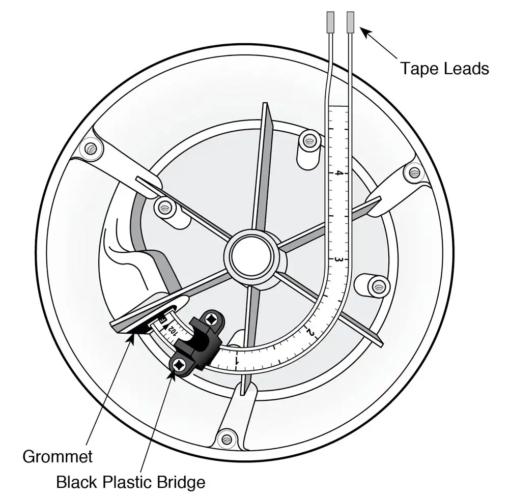
Inside View of Mk3 107/Mk2 101 P7/101D/201/105 Reel Hub
4. Undo the two screws from the black plastic bridge holding the tape inside the reel hub, and remove the top piece of the bridge.
5. For the Mk2 107, 122, and Mk1 101 P7, use the wire cutters to cut the old Tape Molex Connector from the old tape. Remove the ground wire from the 122 Tape Molex connector by pushing out the pin. Pull the old tape through the grommet and remove it from the reel.
6. For the Meters where the tape leads were connected to the circuit board, simply pull the old tape through the grommet and remove it from the reel.
Note:
The replacement tape comes with a new grommet. The old grommet may be replaced with the new one, or left in if not damaged.
7. Feed the new laser tape through the grommet into the reel hub.
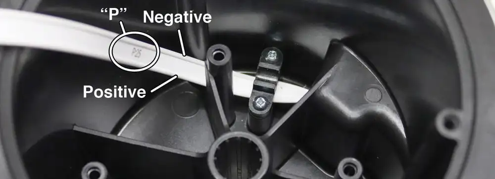
8. For the Meters with a Molex connection, by hand, insert the connector pins into the new Tape Molex Connector housing. The negative connector pin is inserted into the terminal on the pointed side of the Tape Molex Connector housing and the positive pin into the middle terminal. The negative pin is above the numbers (or “P” – see note below) on the tape (see diagram below). The third terminal is left open for the 107 and 101 P7, the ground wire is inserted for the 122.

Note:
There is a “P” etched on the tape to help denote the proper orientation of the tape – top (negative) and bottom (positive) leads.
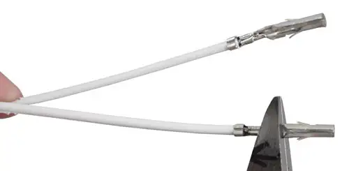
9. For the Meters where tape leads connect to the circuit board, cut the pins on the tape leads at the point shown in the photo below. Use pliers to flatten the pins against the tape leads, so they fit into the terminals on the circuit board (see Step 12).
10. Position the tape inside the reel hub with black plastic bridge over top and refasten the two screws to secure the tape to the reel.
11. For the Meters with a Molex connection, connect the Tape Molex Connector to the Faceplate Molex Connector.
Note:
If you are connecting the Laser Tape to an older style Model 101 that previously used polyethylene tape, you will need to use the Jumper Cable. Attach the 3 pin connection to the Tape Molex Connector, and the 2 pin connection to the Faceplate Molex Connector.
12. For the Meters where tape leads connect to the circuit board, press down on the white terminals on the circuit board and insert the tape leads. Release the terminals and the leads should be secured. For the Mk3 107 and 201, the lead on the top the tape is inserted into the terminal labelled TOP on the circuit board. For the Mk2 101 P7, 101D and 105, the negative lead on the top of the tape is inserted into the terminal with a square etched below it on the circuit board. See following images.

Jumper Cable (New Tape – 3 Pin to 2 Pin) (#110508)

Mk3 107/201 Tape Connection
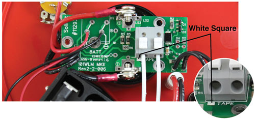
Mk2 101 P7 Tape Connection
13. Attach the probe to the tape seal (existing or replacement probe). See separate probe replacement instructions.
14. 101 P7/101D/107/201: With the probe in a glass of tap water, turn the Meter ‘ON’. If the buzzer or light do not activate, or the Model 107/201 LCD does not show temperature (or conductivity for the 107), check the probe and tape connections. (Test 101D in Water Level Mode).
122: With the Probe in a glass of tap water and product, turn the Interface Meter to the ‘ON’ position. A steady tone and light indicates a product, while an intermittent tone indicates water. If the buzzer or light do not activate, check the probe and tape connections.
105: Push the plunger in at the bottom of the probe. If the buzzer or light do not activate, check the probe and tape connections.
15. Replace the faceplate on the reel and re-secure the three screws.
16. Slowly wind the tape onto the reel, holding to ensure no slack.
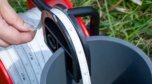
Tape Guide/Datum
A tape guide is provided with each Meter to prevent damage to the tape from rough edges. It also ensures easy, consistent measurements regardless of who takes readings. It can also provide support for hanging small reels on the casing.
Other Options
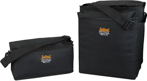
Carrying Case: To help maximize the life of the Meter, optional small and medium padded
nylon carrying cases are available. Their design has a convenient shoulder strap, zippered top
and front pocket, and a grommet in the base to prevent moisture build-up.
Replacement Parts: Replacement probes, tapes, faceplates and other spare parts are available.
Related Products
Bladder Pumps with Easy to Replace Bladder Cartridges
Solinst Bladder Pumps now feature Santoprene® bladder cartridges that are quick and easy to replace in the field – no tools required. PVC Bladder Pumps are low cost and excellent for metals sampling and in harsh, corrosive environments.
101 Power Winder
The 101 Power Winder provides both convenience and ease of use for all Solinst reel-mounted devices. It is lightweight and easy to attach to small, medium or large size Solinst reels, and is simple to adjust to fit other reels in the market. Effortlessly wind longer tape lengths.
(Image shows 101 Power Winder Installed on Solinst Model 101D Water Level DrawDown Meter)
Multilevel Drive Point Piezometers
The 615ML Multilevel Drive-Point System allows monitoring of up to 6 zones in one drive, using ports with a dual barb stem to attach either ¼" or ⅜" OD tubing. Install using extensions and a Manual Slide Hammer, similar to standard 615 installations, for high-resolution vertical groundwater or soil gas profiling.
Measure Water Levels
Without Lowering Equipment Down the Well
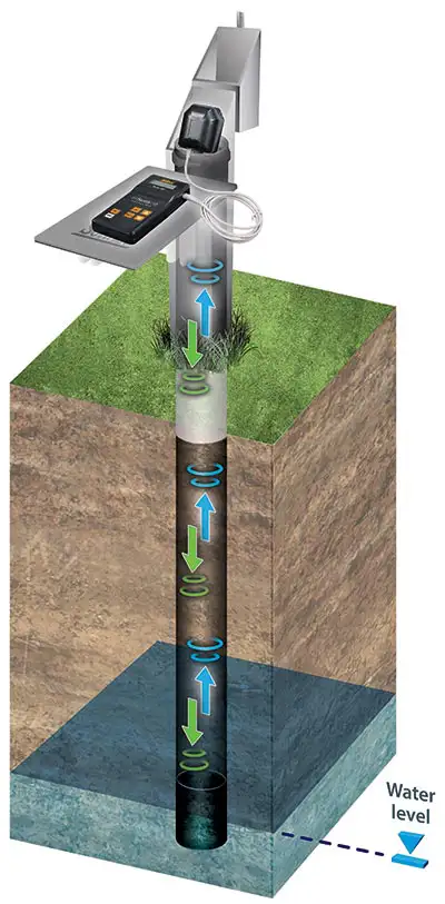
The 104 Solinst Sonic Water Level Meter is a portable, acoustic ranging instrument designed to simply and quickly provide depth to static water level measurements down to 600 m (2000 ft), without the need to lower equipment down a well. Ideal for straight, crooked, narrow, hard to access, or contaminated wells.
Related Blog Posts
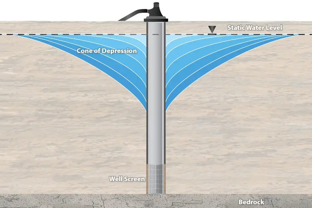
The Importance of Measuring Water Level Drawdown
How Using a Levelogger and 101D Water Level DrawDown Meter Together Provides Essential Data.
What is Drawdown? Drawdown is a change in groundwater level due to an applied stress, caused by events such as: Pumping from a well Pumping from a neighbouring well Intensive water taking from local area Seasonal declines as recharge rates lower....

