Water Level Meter - 12V Power Reel Control Box Assembly Replacement
Tools and Materials Needed
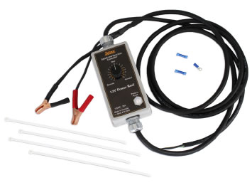
- 101 12V Power Reel Control Box Assembly for Water Level Meter (Spare) (#111427), Includes:
- Control Box Assembly with Power Cord and Mounting Bracket
- 2 x Butt Splice Crimp Terminals
- 1 x Ring Terminal
- 4 x Cable Ties
- Wire Cutter and Stripper
- 7/16" Hex Wrench
- Phillips Screwdriver
- Adjustable Wrench (to 1-1/2")
- Crimping Tool
Instructions
- Disconnect the Power Reel from the power source.
- To remove the Control Box, cut the motor cord and power cord from the old Control Box.
- Use the 7/16" hex wrench to remove the four retaining nuts from each corner of the Control Box mounting bracket. Remove the Control Box.
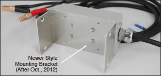
- If you would like to re-use the mounting bracket, flip the Control Box over. Use the Phillips screwdriver to remove the four screws from the mounting bracket, and remove it from the Control Box.
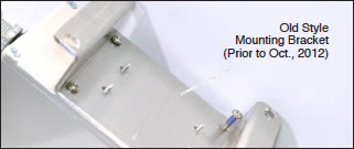
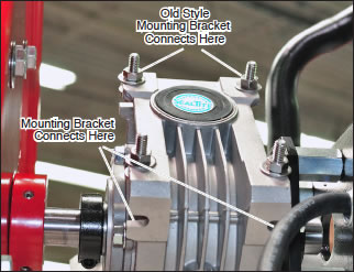
- Mount the new Control Box to the Power Reel, using either the attached mounting bracket, or remove and use the old mounting bracket shown above (if applicable).
- Reuse the four nuts, bolts, and washers to secure the Control Box to the Power Reel, using either the current style mounting bracket that comes with the replacement assembly, or the old style bracket. See photo below for connections.
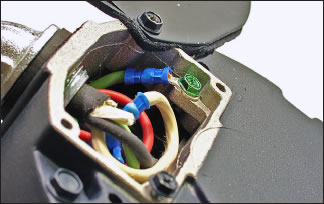
- Use the Phillips screwdriver to open the panel on the bottom of the motor.
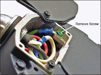
- Use the Phillips screwdriver to undo the screw holding the green wire to the motor.
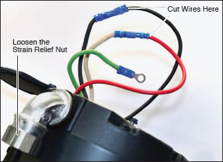
- Pull the wires out from the motor. Use the wire cutters to cut the red and black wires in the motor from the black and white wires of the motor cord. Cut the wires as close to the butt splice crimp terminals as possible.
- Use the adjustable wrench to undo the strain relief nut around the cable, and pull the cable to remove the old motor cord.
- Put the new motor cord through the strain relief.
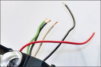
- Strip each of the wires by 10 mm, as shown below.
- Insert the green wire into the new ring terminal. Use the crimping tool to crimp the ring terminal to the green wire. Ensure a good connection.
- Insert the white and red wires into the ends of one of the butt splice crimp terminals. Ensure they are inserted as far as possible into the terminal. Use the crimping tool to secure the wires in the butt splice crimp terminal. Ensure a good connection.
- As above, crimp the black wires together using the other butt splice crimp terminal. Ensure a good connection.
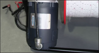
- Connect the green wire to the motor using the screw, as shown in the photo at top left.
- Carefully tuck all wires into the motor and re-secure the panel.
- Tighten the strain relief around the new motor lead.
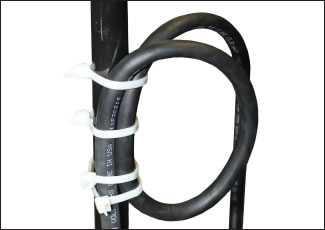
- Use the four cable ties to secure the power cord to the frame, as shown in the photo below.
- Once you are sure all correct connections have been made, and that they are very secure, test the new Control Box (see 12V Power Reel Operating Instructions).
Note:
The Replacement Control Box Assembly comes with a mounting bracket attached, but can be removed, and the old mounting bracket used in its place.
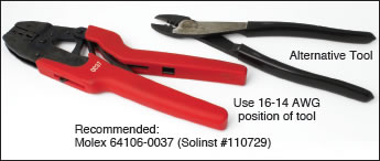
Molex Crimp Tool Options (16-14 AWG)
