122 Interface Meter: Operating Instructions
Operating Principle
The Solinst Model 122 Interface Meter has a narrow 5/8" (16 mm) diameter probe and uses laser-marked PVDF flat tape. It is certified to CSA Standards, for use in hazardous locations Class 1, Div. 1, Groups C & D T3C, and is ATEX certified under directive 94/9/EC, as II 3 G Ex ic IIB T4 Gc. It has an infra-red circuit which detects the presence of a liquid. A conductivity circuit differentiates between conductive liquid (water) and non-conductive liquid (LNAPL or DNAPL product).
Equipment Check
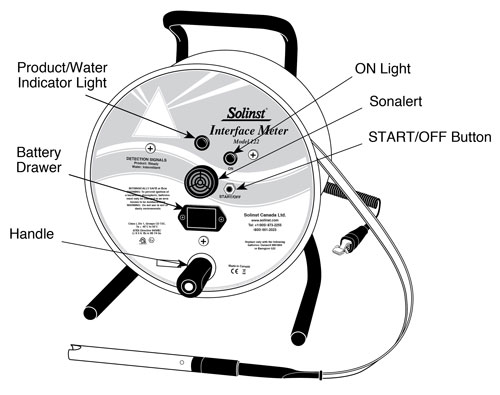
Before beginning any measurements, check the electronics and battery condition by pushing the ‘START/OFF’ button. Five quick beeps with the green light flashing, indicates that the meter is functional. A flashing green light every second indicates the meter is on. It will automatically turn off after 5 minutes to preserve battery life.
Using the Tape Guide
The tape guide has been designed to:
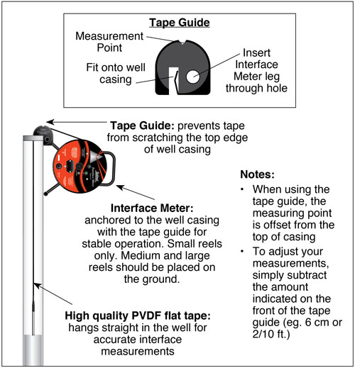
- The tape guide has been designed to: improve accuracy when reading interface measurements; to prevent the laser-marked PVDF flat tape being cut by well casing; and to allow the tape and probe to hang straight from the side of the well.
- If interface measurements are being taken in a 2" dia well then simply fit the small end of the tape guide onto the edge of the well casing.
- Insert the leg of the Interface Meter into the hole on the Tape Guide (small reels only).
- Once inserted, rest the Interface Meter on the side of the well casing.


