Tools and Materials Needed
- 3/32" Allen Key
- Small Utility Knife
- 9/64" Allen Key
- Cotton swab
- Distilled water
- Any suitable plastic adhesive (e.g. silicon)
Instructions
Note:
These instructions are for Solinst Model 464 125 psi Electronic Pump Control Units sold up until January 2016.
- Turn the Control Unit off and remove the batteries.
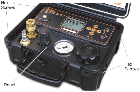
- Use the 3/32" Allen key to undo the four hex screws on the sides of the Control Unit.
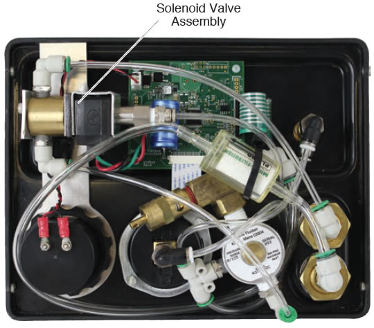
- Remove the panel from the Control Unit and flip it over to access the Solenoid Valve Assembly.
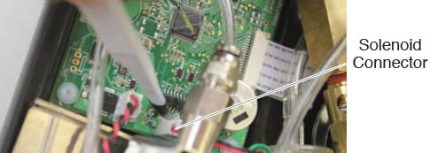
- Use the small utility knife to break any adhesive seal that is holding the Solenoid connector to the circuit board.
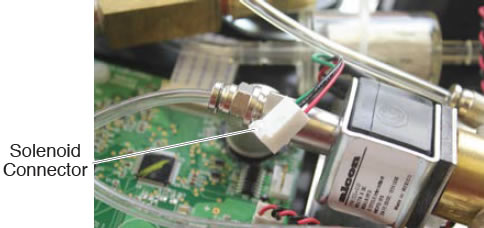
- Carefully, pull to remove the Solenoid connector from the circuit board.
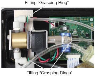
- Remove the tubing from the three fittings on the Solenoid Valve Assembly, by pushing on the "grasping ring" on the fitting (to release tubing) and pulling the tubing out.
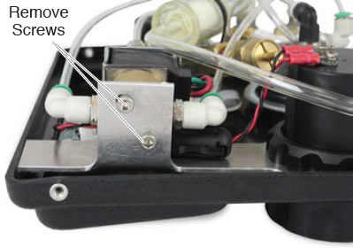
- Use the 9/46" Allen key to remove the two screws holding the Solenoid Valve Assembly to the bracket.
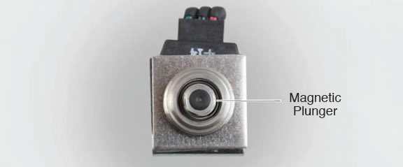
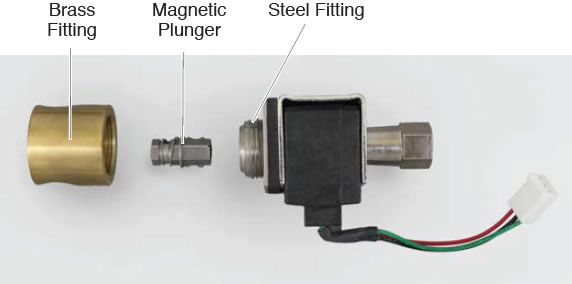
- By hand, unscrew the brass fitting from the Solenoid Valve Assembly, and pull out to remove the magnetic plunger from the steel fitting.
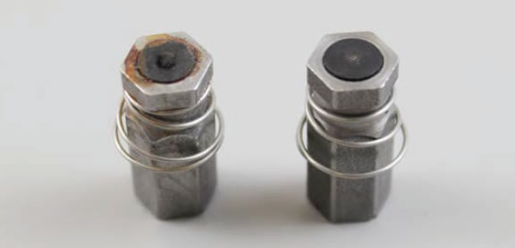
- Inspect the small rubber circular pad on the end of the plunger. If this pad is damaged, dented, etc., the Solenoid will not seal properly, therefore you may need a new Solenoid Valve Assembly. (Contact Solinst). See photo below comparing a damaged pad to a pad in good condition.
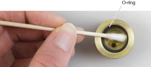
- To clean the Assembly, use a cotton swab and distilled water to clear any debris and dirt from inside the brass fitting, around the o-ring, steel fitting and from the magnetic plunger.
- Ensure the o-ring is properly seated inside the brass fitting. Insert the magnetic plunger back into the Solenoid Valve Assembly, and screw the brass fitting back onto the Assembly.
- Mount the Solenoid Valve Assembly to the bracket using the two screws.
- Push the tubing into the three fittings. Refer to the photo on Page 1, to ensure proper connection.
- Reconnect the Solenoid connector to the circuit board. After connection, add a small amount of adhesive to the outside of the connector to help secure it to the circuit board.
- Place the panel in the Control Unit case and reinstall the four hex screws.
- Reinstall the batteries. Test the Control Unit to ensure proper connections were made and the Solenoid is now functioning.
Note:
The photo above shows the tubing fittings removed from the Solenoid Valve Assembly, you do not need to remove these.
