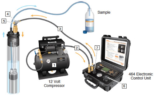
For use with Models 407 and 408 Pneumatic Pumps

Note:
See the Model 464 Electronic Pump Control Unit User Guide for more detailed instructions on setup, operation, care and maintenance.
Model 464 Electronic Control Unit
Gas Sources
- Nitrogen Cylinder
- Compressed Air Cylinder
- Air Compressor
A Nitrogen cylinder is ideal as it is an inert, dry gas, best for pristine samples and longer life expectancy of the Control Unit.
Our 12V Compressor  should only be used in shallow <100 ft (30 m) low flow applications.
Note:
If using a compressor, the drain at the base of the tank should be opened on a daily basis to prevent moisture build-up. The 464 External Filter is recommended. See separate installation instructions for the 464 External Filter.
Pressure
Input pressure supplied from the cylinder or compressor must not exceed 150 psi for the 125 psi Control Unit or 300 psi for the 250 psi Control Unit. The Control Unit will not operate properly at higher input pressures. There is no minimum input pressure for the Control Unit.
Supply Line 
The Control Unit has a built in moisture filter to prevent moisture from the supply line entering the Control Unit. If using a compressor, check and drain moisture build-up in the compressor on a daily basis, according to the manufacturer's instructions. Large compressors should be fitted with a dryer to reduce moisture in supply lines.
Drive Line 
The drive line wellhead connector with exhaust fitting  supplies air or Nitrogen from the Control Unit to the pump and vents from the pump through a diffuser on the
  exhaust fitting. Always use the drive line with the exhaust fitting
  .
.
Venting
If the Control Unit is not cycling from drive to vent, check the battery strength (it is displayed on the top right of the LCD screen). The battery level should be maintained at 60% or higher. If necessary, replace batteries  .
.
If moisture is observed exiting the diffuser  when the pump is venting, remove the pump from the well and check for damage (O-rings, bladder or lines).
Sample Backflow
Moisture in the Control Unit can adversely affect the solenoid, resulting in failure. The best practice is to maintain the Control Unit at a higher elevation than the drive line connection to the wellhead manifold. This height difference limits the potential for backflow into the Control Unit.
With Double Valve Pumps, backflow of sample into the Control Unit can happen and is more apt to occur when the water level is close to ground surface. With Bladder Pumps, leakage in the tubing, a ruptured bladder or damaged O-rings can cause backflow into the drive line and Control Unit.
If water is detected in the Control Unit, it must be disconnected immediately and allowed to dry. Connect a Nitrogen cylinder gas source and let it cycle through the Control Unit, with the drive line unthreaded at the Control Unit. Set a 10 second drive and 2 second vent cycle. This will create a pulse of air that flushes the system. Maintain the cycle of Nitrogen for 10 minutes.
The regulator  may vent air and hiss. This is normal.
Care and Maintenance
Prior to any storage period, we suggest purging your Control Unit with a dry gas, such as Nitrogen. This purging will help to avoid any potential damaging effects from the build-up of moisture after sampling. If your Control Unit was subject to ‘sample backflow’, then the preventative maintenance described under the “Sample Backflow” heading, should be conducted.
If the Control Unit is going to be stored for longer than two months, the four alkaline batteries should be removed to avoid potential leakage.


