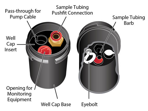

Includes the Well Cap Base, Cap, Insert and Support Hanger Bracket (4" Adaptor also available (#110235))
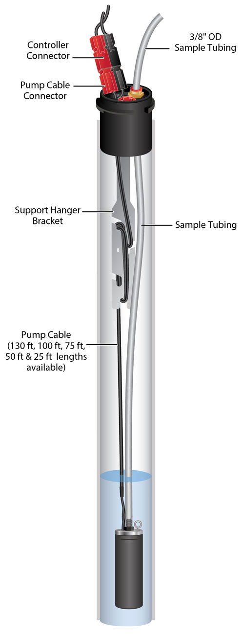
- Wrap the top end of the Pump cable around the support hanger bracket, inserting the cable into the cutouts of the bracket to secure. Leave about 3" of slack in the Pump cable (top end has connectors for the Controller) above the top of the bracket.
- Just above the hanger bracket, slip the Pump cable through the pass-through in the side of the well cap insert and into the opening (tubing pushfit connection on the insert facing up). Line up the insert with the hanger bracket, to avoid twisting the cable.
- Connect the sample tubing from the Pump to the tubing barb on the bottom of the well cap insert. Ensure the tubing is pushed all the way onto the tubing barb.
- Slide the well cap base onto the well casing.
- Lower the pump assembly down the well until the support hanger bracket seats on the shoulder of the well cap base.
- Push a short length of 3/8" OD sample tubing into the pushfit connection on the top of the well cap.
- Connect the Controller to the Pump cable connector and operate the 12V Pump in the same manner as described on Page 1.
- Once finished sampling, release the sample tubing from the pushfit connection by pushing down on both sides of the top ring and pull the tubing out.
- Secure the well cap to the well cap base. Attach an optional padlock if needed.
Note:
The holes in the bracket can accommodate twist ties or zip ties to secure the cable to the bracket, if desired.
Note:
While sampling, the red plug can be removed from the opening in the well cap insert to accommodate other monitoring equipment, such as a Solinst Water Level Meter or Levelogger.


