464 Electronic Pump Control Unit Troubleshooting
Symptom: No air discharge from Control Unit:
Test Solenoid Switch Function
Follow the steps below, and answer the questions to determine if your Solenoid Switch is functioning properly:
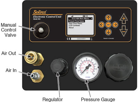
Front of the Model 464 Electronic Pump Control Unit Faceplate
- With an air source connected to the Control Unit, and a flow rate selected and running, can you hear the ‘clicking’ sound of the Solenoid switching with every drive and vent cycle?
- Using the Regulator, adjust the pressure (0 to 100 psi). Does the Pressure Gauge respond with the change?
- Connect an open fitting to the Air Out connection. Push the Manual Control Valve. Air should discharge out through the open fitting.
- No air discharge means that the solenoid is blocked and not functioning, contact Solinst.
Symtpom: Hear an air discharge from below the faceplate:
Check for Leaks
Note:
The Blow off Valve of the 125 psi Control Unit is activated at ~150 psi, and the 250 psi Control Unit at ~315 psi. When activated, the Blow off Valves discharge into the open box area as a burst of air - this is normal. The Regulator of both types of units may hiss - this is normal.
- Disconnect the air supply. Remove the four 3/32" hex screws on the sides of the Control Unit holding the faceplate, and flip for access to the components.
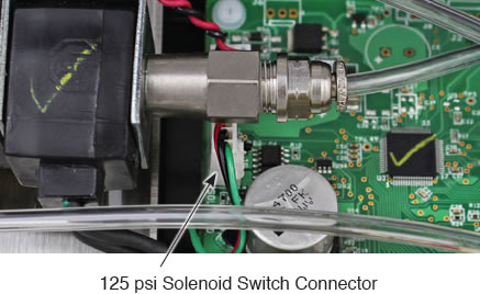
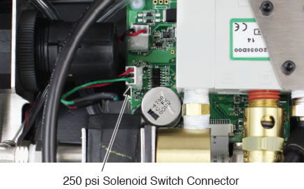
- Ensure a good physical connection of the air line from the Manual Control Valve to the Solenoid Switch (see photos above). The air lines simply push into the fitting to make the airtight connection.
- Reconnect the air supply and adjust the Regulator to 100 psi. Do you hear/see any air leaks?
- If you still hear an air discharge from the back of the faceplate, contact Solinst.
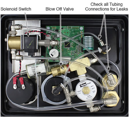
Back of the 125 psi 464 Electronic Pump Control Unit Faceplate
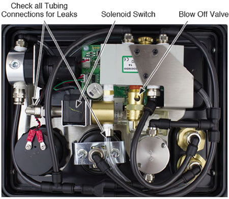
Back of the 250 psi 464 Electronic Pump Control Unit Faceplate (after Sept 2013)
Symptom: Timer Cycles not functioning:
Check and Test the Circuit Board
You can check the Circuit Board to see if the timer cycles for the flow rates are working correctly, by following the steps below:
- Disconnect the air supply. Remove the four 3/32” hex screws on the sides of the Control Unit holding the faceplate, and flip for access to the components.
- Ensure a good physical connection of the two white connectors into the Circuit Board.
- Is there any discolouring/staining on the Circuit Board?
- Use a volt meter across the Battery Terminal Connections to ensure it reads 8 Volts.
- Set the drive/vent cycle to 3 seconds, and start the Control Unit (See 464 User Guide).
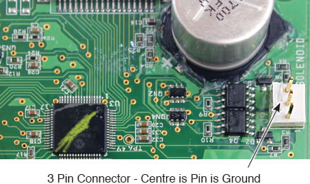
- Disconnect the Solenoid Switch from the Circuit Board.
You will see 3 pins on the Circuit Board - the centre pin is
the ground.
- Using a volt meter set to “AC”, connect the black lead of the volt meter to the centre ground pin, and the red lead to either one of the outside pins.
- You should see a ‘pulse’ every 3 seconds of about 1 volt. This means the connection on the Circuit Board is okay.
- If there is no pulse, contact Solinst.
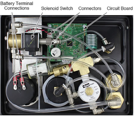
Back of the 125 psi 464 Electronic Pump Control Unit Faceplate
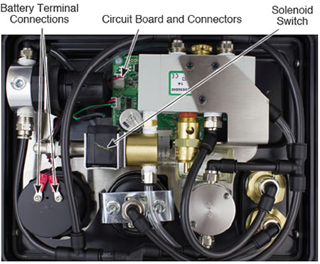
Back of the 250 psi 464 Electronic Pump Control Unit Faceplate
(after Sept 2013)
