Tools and Materials Needed
- 464 Electronic Pump Control Unit Solenoid Valve Assembly - 125 psi (Spare) (#111383)
- 3/32" Allen Key
- Small Utility Knife
- 7/16" Wrench
- 9/64" Allen Key
- Teflon® Tape (for stainless steel threads)
- Any suitable plastic adhesive (e.g. silicon)
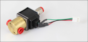
464 Solenoid Valve Assembly - 125 psi (Spare)
Instructions
- Turn the Control Unit off and remove the batteries.
- Use the 3/32" Allen key to undo the four hex screws on the sides of the Control Unit.
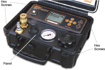
- Remove the panel from the Control Unit and flip it over to access the Solenoid Valve Assembly.
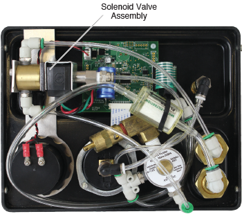
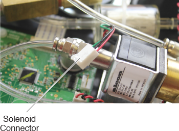
- Use the small utility knife to break any adhesive seal that is holding the Solenoid connector to the circuit board.
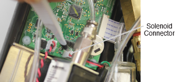
- Carefully, pull to remove the Solenoid connector from the circuit board.
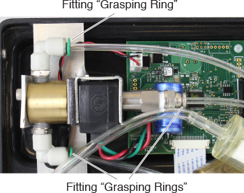
- Remove the tubing from the three fittings on the Solenoid Valve Assembly, by pushing on the “grasping ring” on the fitting (to release tubing) and pulling the tubing out.
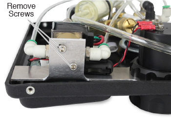
- Use the 9/46" Allen key to remove the two screws holding the old Solenoid Valve Assembly to the bracket.
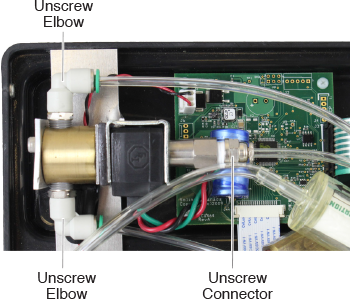
- Use the wrench to unscrew the two elbow connectors and one stainless steel connector from the old Solenoid Valve Assembly.
- Remove the three red plugs from the new Solenoid Valve Assembly
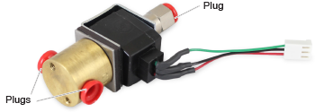
- Screw the two elbow connectors and one stainless steel connector into to the new Solenoid Valve Assembly.
Note:
Wrap Teflon tape around the threads of the stainless steel connector.
- Mount the new Solenoid Valve Assembly to the bracket using the two screws.
- Push the tubing into the three fittings. Refer to the photo above to ensure proper connection.
- Reconnect the Solenoid connector to the circuit board. After connection, add a small amount of adhesive to the outside of the connector to help secure it to the circuit board.
- Place the panel in the Control Unit case and reinstall the four hex screws.
- Reinstall the batteries. Test the Control Unit to ensure proper connections were made when replacing the Solenoid Valve Assembly.


