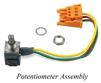
Tools and Materials Needed
- 410 Potentiometer Repair Assembly for the Peristaltic Pump (#109588)
- 2 mm (5/64" Allen Key) (or Small Flat Screwdriver)
- 12.7 mm (1/2") Wrench or Pliers
- 8 mm (5/16") Socket Wrench (or Slot Head Screwdriver)
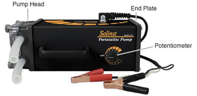
Solinst Model 410 Mk4 Peristaltic Pump (#112981)
Instructions
- Disconnect the Pump from the power supply.
- Use the socket driver to remove the four screws from the End Plate (opposite end from Pump Head).
- Carefully slide the Control Board out of the enclosure.
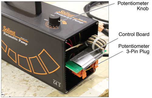
- Use the Allen key to undo the screws on the Potentiometer Knob and remove the Knob.
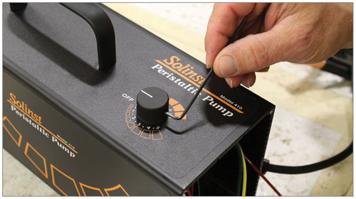
- Use the wrench to unscrew the Retaining Nut from the Potentiometer (on the top of the pump housing), remove the small washer and push the Potentiometer into the housing.
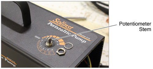
- Unplug the 3-Pin Plug of the old Potentiometer Assembly from the Control Board by pressing the sides and pulling out from the Board.
- Plug the 3-Pin Plug from the new Potentiometer Assembly into the Control Board. The plug is polarized so there is no risk of reverse polarity.
- Slide the Control Board into the enclosure in the slots, plugs facing down and the wires of the Potentiometer Assembly to the inside of the Control Board.
- Place the Potentiometer Stem through the opening in the pump housing, the side of the potentiometer with the wires facing out. Rotate the Potentiometer stem to the center position, and align with "OFF". Replace the small washer and tighten the Retaining Nut on the Potentiometer.
- Slide the Potentiometer Knob onto the Potentiometer Stem and align the white indicator with "OFF".
- Retighten the two screws on the Potentiometer Knob; do not over-tighten. Ensure when the Knob is turned, it rotates and stops at both "5" markings on the pump.
- Carefully push all wires into the housing and screw the End Plate back on the Pump.

