WARNING:
Before driving into the ground, be sure you have under-ground service clearance to avoid cables, gas lines, pipes, etc.
Note:
Always follow local health and safety protocols for worker safety and personal protection
Component List
- 615 ML Multilevel Drive-Point Tip
- 615 ML Multilevel Drive-Point Ports (maximum 3 when using 3/8" OD tubing, maximum 6 when using 1/4" OD tubing)
- Extensions (suitable to reach the required depth)
- Couplings (for connecting extensions together)
- 2 Pipe wrenches
- Sample tubing (suitable to reach the required depth for each port)
- Tubing cutter
- Zip/cable ties (for tubing management) set of 10 (108885)
- Manual Slide Hammer
- Drive Head Assembly
Includes:
Drive Head, Drive Extension & Tubing Bypass
- 1/4" Tube caps (set of 10) 111904 or 3/8" Tube caps (set of 10) 109188
Note:
: Drive-Points are designed for single use installations (temporary or permanent). They are not meant for reuse.
Installation with a Manual Slide Hammer
- Ensure that all components are clean prior to use.
- Thread the Multilevel Drive-Point Tip into the bottom of the Multilevel DrivePoint Port that will be the lowest in the assembly, or use a coupling to connect an extension to the tip, then thread the port onto the extension. Tighten components with pipe wrenches.
- Cut a piece of tubing for each port to the depth of the proposed port installation plus an additional 1.5 m (5 ft). Identify the top of tubing. Consider cutting the tubing tops to different lengths (e.g. longest tubing length is deepest port; shortest denotes shallowest port).
- Connect the 3/8" OD or 1/4" OD sample tubing to the barbed port stem by pushing firmly until the tubing reaches the base of the barb – 1/4" OD tubing will reach the base of the first barb and 3/8" OD tubing will reach the base of the second barb.
- Slide a length of extension pipe over the tubing, and thread it firmly into the port. Allow the free end of the sample tubing to turn freely to avoid twisting within the extensions. Longer tubing lengths may require rotating the excess tubing by hand.
- Continue adding extensions and couplings to the depth required, or suitable 'working height' to use the Slide Hammer assembly (3 ft. long). Use pipe wrenches on all joints
Important:
There needs to be at least a 6" extension between ports. The Tubing Bypass can not be threaded directly to a port.
- Slide the Tubing Bypass over the tubing and tighten it firmly onto the extension pipe, with the tubing extending through the side hole.
WARNING:
When connecting or removing the Tubing Bypass, allow the sample tubes to turn freely to avoid twisting. Longer tubing lengths may require rotating the excess tubing by hand.
- Slide the hammer over the Drive Head and operate the hammer to drive the device until only about 15 cm (6") of the extension pipe below the Tubing Bypass remains above the ground.


WARNING:
For health and safety reasons, it is strongly suggested that only a suitable slide hammer be used. Sledge hammers are not suitable and can cause serious physical injury.
- Remove the hammer, then remove the Drive Head Assembly.
- Slide a coupling over the tubing and tighten firmly onto the previous extension pipe. Slide the next extension over the tubing and tighten it securely. Continue adding couplings and extensions (as described in steps 6–9) until you are ready to connect the next port.
- Thread the second port over the tubing and tighten onto the extension, then connect the tubing to the port stem.
- Before threading the next extension over the tubing, use a zip/cable tie to group/bundle the two tubes together close to the port stem.
- Ensure the two tubes are not twisted, but parallel. Use cable ties along the length of the tubing, as required, to keep the tubes from twisting (keep them loose enough to be able to slide along the tubing).
- Slide an extension over the tubing and using the cable ties to assist with tubing management, slide them along the tubing in front of the extension.
- Once the extension and cable ties reach the port stem, cut the ties from around the tubing and connect the extension to the port.
- Continue connecting couplings and extensions (as described in steps 6–9), using cable ties for tubing management, until you are ready to connect the third port.
- Before connecting the third port, pay close attention to where the port stem is. Ideally, when installing 3 tubes, you'd like to create an evenly spaced triangle formation with the three tubes/port stems (similarly, create an evenly spaced formation if using more than three ports with 1/4" tubing).
- If you are using 1/4" sample tubes, continue adding ports (connect tubing to each one) and extensions as previously described, until the desired installation depth is reached.
- Pull up on each tube to straighten and ensure none are twisted or kinked.
- To identify port depths, consider cutting each tube at a different length (e.g. shortest tube = shallowest port). Attach a tube cap to each sample tube to complete the installation.

Use Cable Ties To Bundle Tubing When Installing
615ML Multilevel Drive Point Piezometer Sampling Ports.

Push And Move The Cable Tie Along The Tubing To Keep The Tubing Grouped And Will Avoid Twisting.

Installation Tip Is To Keep Tubing From Twisting
Before Adding Drive Point Extensions To Your
615ML Multilevel Drive Point Piezometer.
Important:
Do not hold the tubing while threading the extension into the port; you can untwist the free ends of the tubing after the extension is connected, if required.

Cut And Remove The Cable Ties And Slowly Slide The
615ML Multllevel Drive Point Piezometer Extension Into Place And Tighten.
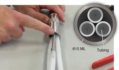
Installation Tip Is To Create A Triagle Formation
With The Tubing
If You Are Looking At It From The Top View
When Installing The 615ML Multilevel Drive Point Piezometer.
