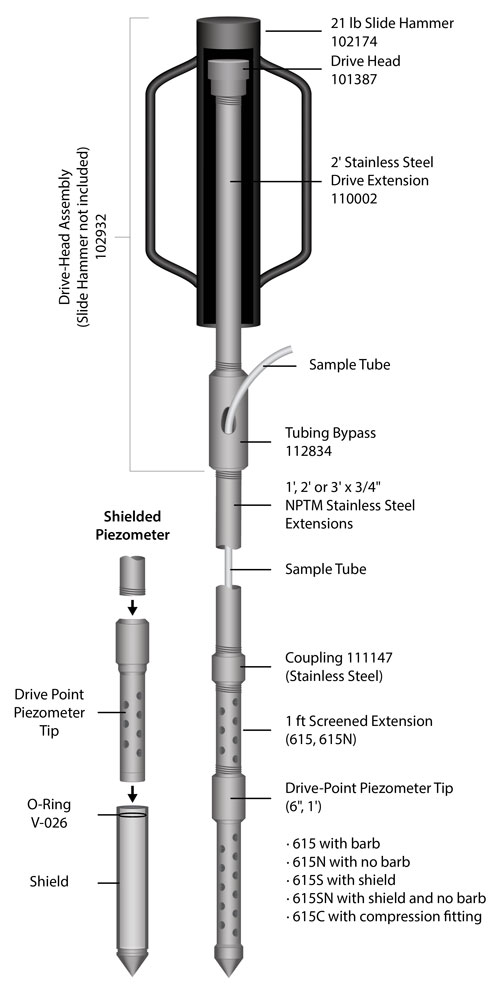
Model 615, 615C, 615N, 615S & 615SN (with Slide Hammer)
WARNING:
Before driving into the ground, be sure you have underground service clearance to avoid cables, gas lines, pipes, etc.
Component List
- Drive-Point Piezometer Tip
- Screened Extensions
- Extensions (suitable to reach the required depth)
- Couplings (one required for each extension)
- Manual Slide Hammer
- Piezometer tubing (suitable to reach the required depth)
- Drive Head Assembly
Includes: Drive Head, Drive Extension & Tubing Bypass - Delrin Cap (111148)
Installation with a Manual Slide Hammer
Note:
Drive-Points are designed for single use installations (temporary or permanent). They are not meant for removal and reuse.
- Ensure that all components are clean prior to use.
- If using piezometer tubing, cut it to the depth of the proposed installation plus an additional 5 ft (1.5 m).
- If using a 615 or 615S, Connect the 5/8" OD piezometer tubing to barbed fitting on the Drive-Point Piezometer Tip by pushing firmly until the tubing reaches the base of the fitting.
Or, if using a 615C, loosen the compression fitting and insert the 1/4" piezometer tubing. Tighten 1 and 1/4 turns past finger tight to properly secure the tubing in the fitting. - Slide a length of extension pipe over the tubing, and thread it firmly onto the Drive-Point Piezometer Tip. Tighten with a pipe wrench.
If using a 615N or 615SN, then you will not be working with tubing. Simply thread the extension pipe onto the Piezometer Tip.
WARNING:
When connecting or removing the Tubing Bypass, it is very important to hold the tubing to prevent it from turning. Failure to do so may result in the tube being dislodged from the Drive-Point Tip.
- Hold the tubing to prevent it from turning, then slide the Tubing Bypass over the tubing and tighten it firmly onto the extension pipe, with the tubing extending through the side hole.
- Slide the Slide Hammer over the Drive Head and operate the hammer to drive the device until only about 6" (15 cm) of the extension pipe below the Tubing Bypass remains above the ground.
WARNING:
For health and safety reasons, it is strongly suggested that only a suitable slide hammer be used for Drive-Point Piezometer installations. Sledge hammers are not suitable and can cause serious physical injury.
- Remove the hammer, then holding the tubing to prevent it from turning, remove the Drive Head Assembly.
- Slide a coupling over the tubing and tighten firmly onto the previous extension pipe. Slide the next extension pipe over the tubing and tighten it securely.
- Repeat steps 5 through 9 until the desired sampling depth is reached.
- Cut the piezometer tubing to fit flush to the top of the extension pipe. Attach a cap to the top of the piezometer to complete the installation.

Important Note about Shielded Piezometers
- Before driving into the ground, ensure that the shield is on firmly and the o-ring seats properly.
- Drive the Piezometer an equal length past the desired depth, then pull back/up to expose the inlet.
- 1ft (102412) and 6" (104370) Replacement Shields are available when re-using the Drive-Point Piezometer.


