Typical Installation Using
Manual Slide Hammer
Operating Principles
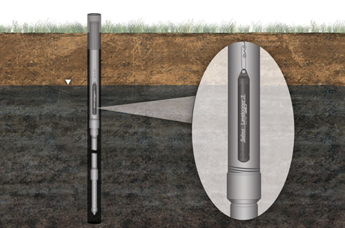
To install a Solinst Levelogger within a Drive-Point Piezometer, a section of 1" extension pipe is required to accommodate the 7/8" diameter Levelogger.
To minimize friction during installation with a manual slide hammer, the section of 1" pipe should be installed as close to ground surface as possible (i.e. install the Levelogger as shallow as possible, but deep enough so it remains submerged throughout the monitoring period).
Use 3/4" extensions and couplings to get the piezometer tip as deep as possible before requiring the 1" section. When installing the piezometer using a manual slide hammer, depth limitations will vary with soil conditions.
Component List
- 1" NPTF to 3/4" NPTM Reducing Couplings (set of 2) (#113470 or
- 1" BSPTF to 3/4" NPTM Reducing Couplings (set of 2) (#114259)
- 615N or 615SN (no tubing barb) Piezometer Tip (6" or 1 ft)
- 3/4" NPT Extension(s) and Couplings
- 1" NPT or BSPT Extension(s) and Couplings (sourced locally)
- Drive Head Assembly (#102932)
- Manual Slide Hammer (#102174)
Note:
Never use the slide hammer with a Levelogger installed.
Installation
- Ensure that all components are clean prior to use.
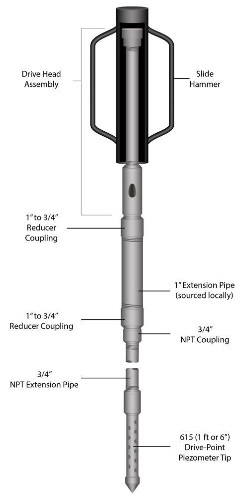
- Follow the 615 Drive-Point Piezometer instructions to install the piezometer tip and 3/4" extension pipe section, until only about 6" (15 cm) of the extension pipe remains above ground.
- Thread on a 3/4" coupling. Use pipe wrenches to tighten.
- Thread one of the 1" to 3/4" reducer couplings into the 3/4" coupling and tighten.
- Thread a 1" extension pipe into the reducer coupling and tighten it securely.
- Thread the second reducer coupling to the end of the 1" extension pipe.
- Thread the drive head assembly onto the reducer coupling.
- Slide the hammer over the drive head and operate the slide hammer to drive the device until only about 6" (15 cm) of the 1" extension pipe below the drive head assembly remains above the ground.
- Remove the hammer, the drive head assembly, and the reducer coupling.
- Thread a 1" coupling onto the 1" extension pipe, then the next extension pipe into the coupling. Tighten securely.
- Repeat steps 6 through 10 until the desired final depth is reached.
- Install the Levelogger. See the Levelogger Series User Guide for more information on Levelogger installation.
- Finish the installation by capping off at the top (you can temporarily use a reducer coupling and a 3/4" delrin cap (# 111148)).
Note:
The reducer coupling will not thread directly to a 615SN Shielded Drive-Point Piezometer. A 3/4" NPT extension pipe and coupling must first be connected.

Levelogger Installation Just Below Lowest Expected Water Level


