Marking and Cutting the Tubing
Depth Discrete Groundwater Monitoring
Reduce Costs and Field Time
Step 1) Uncoil Tubing
Uncoil the CMT tubing on the ground or other flat surface. Stretch out a measuring tape at least as long as the depth of the well, next to the CMT tubing.
Note:
Newly uncoiled CMT tubing has a memory which can make it difficult to lay out straight. Sand bags help to hold down the ends of the tubing. The “memory” goes away relatively quickly, especially in warm weather. Placing the tubing on black plastic sheeting can warm the tubing, helping it straighten out more quickly.
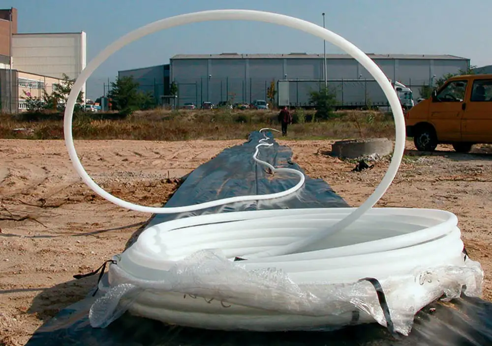
Figure 3 – Solinst CMT Multilevel System Tubing
Step 2) Indicate Ground Surface on Tubing
Allowing for your desired wellhead stick up (2-3 feet above ground surface), place the end of the measuring tape below the length of tubing you want above ground. This is your measuring point which represents ground surface and all depths below this point use depths below ground surface.
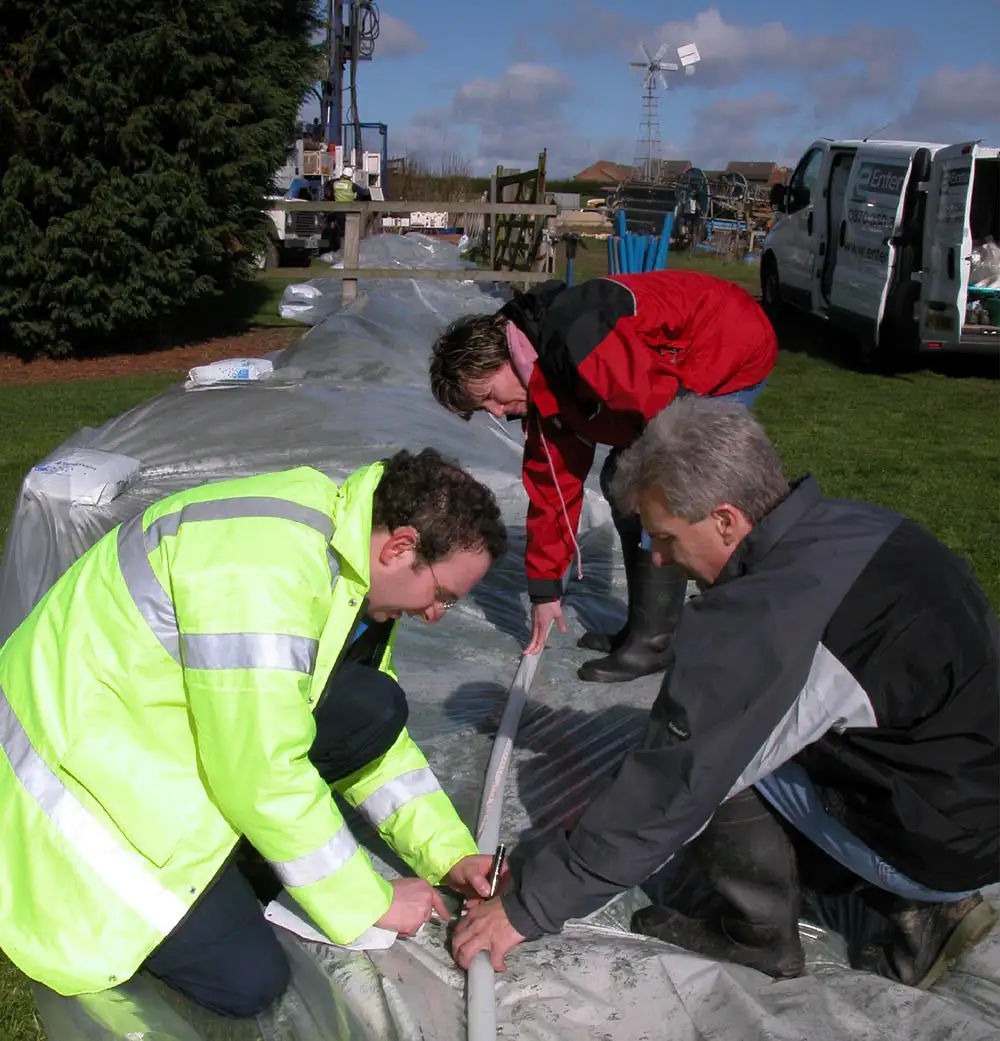
Figure 4
Step 3) Locate Channel 1 Identifier
The next step is to make marks on the CMT tubing at the depths corresponding to the midpoint of the desired monitoring ports. Before you do this, you will note that there is a faint channel identifier, a low profile repetitive marking “<< CMT >>” that runs along the entire length of the CMT tubing opposite one of the outer channels. This channel identifier facilitates identification of the various internal channels anywhere along the length of the tubing The channel that has the identifier is always Channel 1. By convention, Channel 1 corresponds to the shallowest monitoring zone. The other five outer channels are numbered clockwise from 2 through 6 as you are looking down on the completed well from above. The center channel is Channel 7 and is always the deepest monitoring zone.
Note:
The channel identifier on the CMT tubing is intentionally subtle to avoid being a conduit for vertical leakage.
Step 4) Mark Monitoring Port 1
Make a mark across Channel 1 (Figure 5) on the exterior of the CMT tubing at the depth corresponding to the center of the uppermost monitored port (23 feet below ground surface in our hypothetical example; Table 1). A permanent marker or a “China marker” wax pencil works well for this. Write “Port 1″ on the CMT tubing about 6” above the mark.
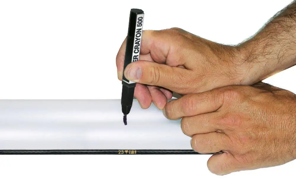
Figure 5 – Marking CMT Tubing
Note:
The Channel 1 identifier is a low profile repetitive marking
Step 5) Mark Port 1 for Port Cutting Guide
Next, draw a line along the Channel 1 identifier (i.e., parallel with the tubing extending approximately 6″ above and 6″ below the depth mark (Figure 6). You will use this line (and other similar lines drawn at the other port depths to index the Port Cutting Guide. This ensures that you cut holes only in the intended channels corresponding to the desired monitoring zones (as shown in Table 1).
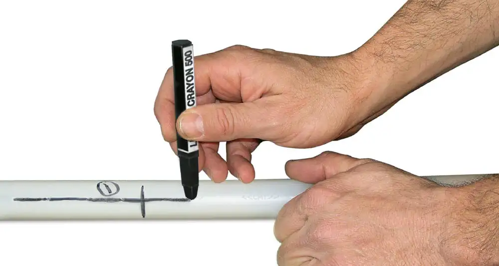
Figure 6 – CMT Port Marking Setup
Note:
The next series of instructions use hand tools and materials that are sharp. Use proper protective equipment. Work safely.
Step 6) Mark all Ports and Cut Tubing at Deepest Port
Make similar marks at the depths corresponding to the next five monitoring zones (i.e., 34, 48, 55, 69, and 77 feet below ground surface). Make the marks identical to the ones you drew at Port 1. That is, draw the depth mark across Channel 1 and draw the longitudinal line along the Channel 1 identifier. The Port Cutting Guide has been indexed so that it always references the Channel 1 identifier when it is used to cut holes in the five other outer channels. Label these depth marks as Port 2, Port 3, etc…..about 6″ above each mark. Finally, make a mark at the depth of the deepest monitoring port (i.e., the internal channel, Port 7), which is also the bottom of the well, at 92 feet. Cut the CMT tubing at this mark using a hacksaw, sharp knife, or PVC cutter.
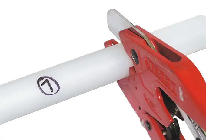
Figure 7 – Cutting the CMT Multichannel Tubing
Step 7) Complete Design
The design of the well has now been transferred to the CMT tubing
