401 Waterloo System: Assembly Manual 9.0 Wellhead Manifold Completion
9.0 Wellhead Manifold Completion
9.1 Standard Option
Tools and accessories required: tubing cutter, Phillips screwdriver, PVC pipe saw/cutter.
Determine the desired ‘stick-up’ of PVC casing when the system is at its final depth. If applicable, cut the last piece of PVC Riser to the appropriate length and install the Riser Clamp to achieve your desired ‘stick-up’. The Riser Clamp ensures that the proper stick-up is maintained when the Waterloo System is hung. For safety, use a casing clamp and lower the System to depth. If you have used the SS support cable to lower the System, be sure to continue to use this cable to support the System during the packer expansion (up to three days).
Note:
Allow for at least 20″ (50cm) of clearance above the final PVC Casing ‘stick-up’ and the underside of your protective outer enclosure. This will ensure that you do not pinch the monitoring tubes and cables above the completed manifold.
Note:
Take a water level reading in the borehole and record it in the “Water Level at End” box on the Installation Log, after the System is installed to depth.
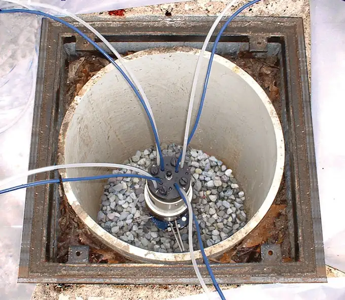
Figure 9-1 Tubing Organized Around the Wellhead
Remove the two Phillips screws from the white protective housing of the Wellhead Manifold Base and then remove the Manifold Base from the 4″ (100 mm) diameter protective housing. Install this lower (black) portion of the Manifold (small end first) onto the completed installed PVC Casing. Using the numbered Wellhead as a guide, separate and organize the tubes and/ or cables into a ‘wagon wheel’ pattern around the Wellhead.
Thread the open tubes, sample tubes (white) and/or blue VWT cables through the numbered Wellhead. Re-attach and screw the numbered Wellhead to the Manifold Housing at the Wellhead.
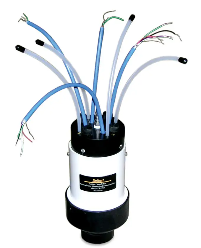
Figure 9-2 Tubing and Cables Installed Through a Wellhead
9.2 Multipurge Option
If pumps are used, follow the steps above, but before attaching the Wellhead, choose one drive line tube and hold it up against the 4″ (100 mm) diameter white protective housing which is at its final elevation at the wellhead. Trim the red drive line tube at a point about 2″ (50 mm) above the white protective housing. Insert this tubing end into the white (translucent) plastic compression fitting on the base of the numbered Wellhead. You should be able to see the red tubing pass through this fitting. Hand tighten the fitting. Repeat this procedure on the remaining drive tubes. Re-attach the numbered Wellhead to the Manifold Housing at the Wellhead and tighten the screws.
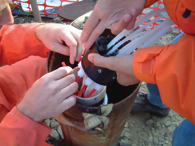
Figure 9-3 Pump Tubing Being Attached to a Wellhead
9.3 Wellhead Protection
Allow sufficient wellhead access when you install a protective cover over the well. Use a large well cover to allow plenty of room to access the wellhead. The following diagrams show some suggested completions for the 401 Waterloo Multilevel System. These enclosures are not available at Solinst, however they are available from most drilling contractors.
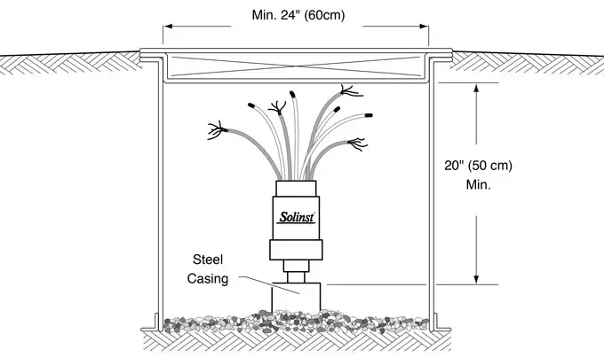
Figure 9-4 Waterloo Multilevel Wellhead Inside Flushmount Vault
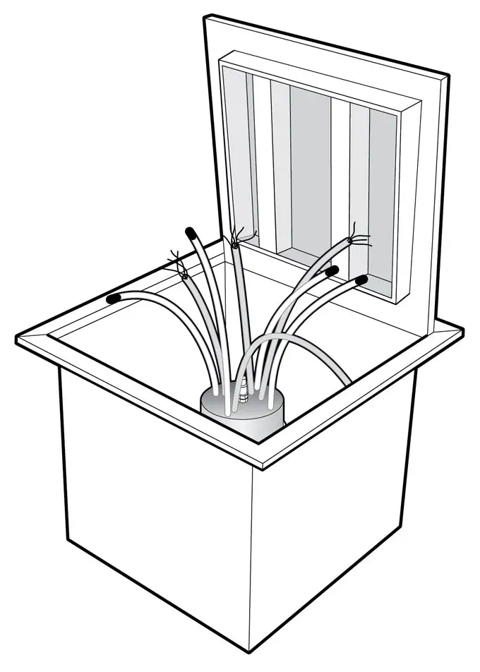
Figure 9-5 Typical Road Box or Vault
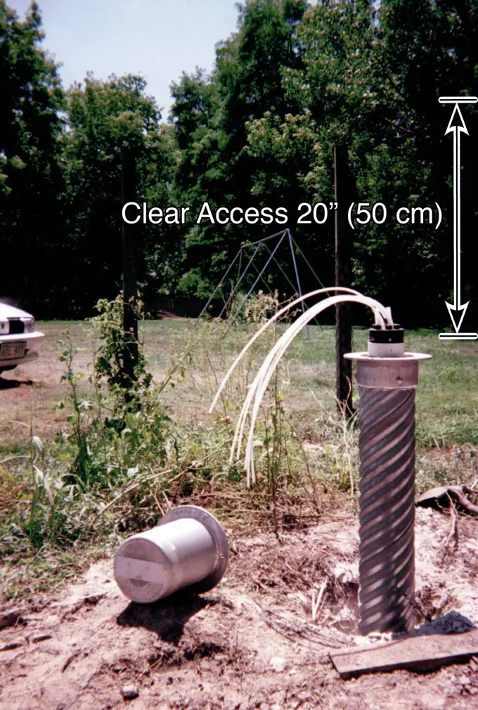
Figure 9-6 Above ground completion Minimum 6″ dia. (15 cm) and 20″(50 cm) clearance is required

