401 Waterloo System: Assembly Manual 6.0 Port Connections
6.1 Attaching Open Tubes
Tools and accessories required: Oetiker pliers, tubing cutter, black electrical tape, rod/broom handle, sand paper.
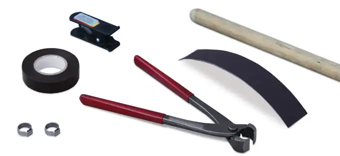
Figure 6-1 Tools and Accessories Required
Beginning with the deepest Port (Port 1), stand at the borehole holding the spool of tubing(1/2″OD x 3/8″ID or 5/8″OD x 1/2″ID). A broom handle or equivalent pole works well to hold the spool. A second person will ‘walk’ the end of the tubing to the measured reference mark (Section 4.0). Once the tubing end is pulled to this reference mark, label the tube about 1 ft. (30 cm) from the tubing end. Black electrical tape works well. Use the black tape to wrap the number of bands corresponding to the Port number around the tubing end (i.e. 1 band of black tape represents Port 1). Cut the tubing at the spool.
1/2″OD x 3/8″ID or 5/8″OD x 1/2″ID tubing can be used. The 1/2″OD tubing is clamped directly onto the Port Stem with an Oetiker #14 clamp, while the 5/8″OD tubing fits over a 3″ length of 1/2″OD tubing before being clamped to the Port Stem with an Oetiker #17 clamp.
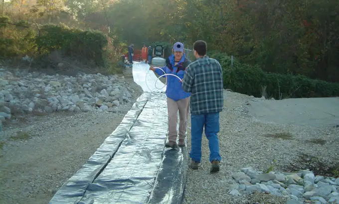
Figure 6-2 Tubing Being Pulled to Reference Mark
Note:
Remember to label each tubing/cable end.

Figure 6-3 5/8″OD x 1/2″ID tubing attached over 3″ of 1/2″OD x 3/8″ID tubing to Port Stem Using Oetiker #17 Clamp
At the next Port, roll off the tubing to the end of the previous cut tubing length, and cut at this new reference mark. Use this reference for the remaining Ports, so as more Ports are added the tubing and cable ends will meet at the same point. Remember to label each length of tubing as you progress.
Be sure there is a clean cut to the tubing end at the Port. Place one single ear Oetiker #14 clamp over the tubing and push the tubing end onto the stainless steel Port Stem. Using the Oetiker pliers, squeeze the clamp ‘shoulders’ together to securely attach the tubing to the stem.
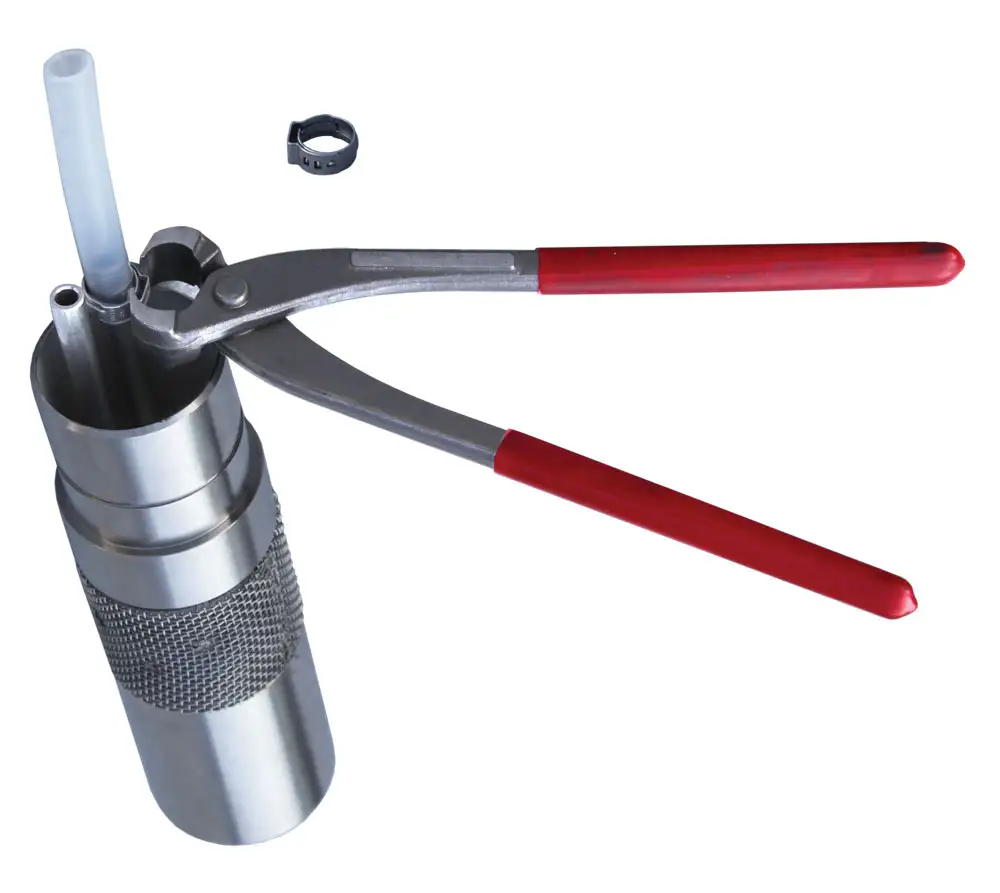
Figure 6-4 1/2″OD x 3/8″ID tubing attached to Port Stem Using Oetiker #14 Clamp
Note:
If using 5/8″OD tubing, a 3″ length of 1/2″OD tubing has to be first pushed onto the Port Stem. Then the 5/8″OD tubing is pushed over the 1/2″OD tubing and clamped to the Port Stem with an Oetiker #17 clamp (see Figure 6-3).
6.2 Attaching Vibrating Wire Transducers (VWT)
Tools and accessories required: 11/16″ (18 mm) and 5/8″ (16 mm) wrenches.
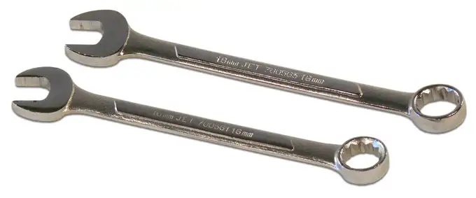
Figure 6-5 Tools and Accessories Required
Each one of the VWT’s cables has been cut to the length requested in the original order. This length also includes an additional 10% contingency. The total cable length is labeled on the cable’s end.
Match the serial number on the VWT body with the labeled cable end, and its corresponding “Vibrating Wire Transducer Calibration Report” provided in the shipment (see Appendix II).
Note:
Match the serial number on the body of the VWT with the label at the end of the cable.
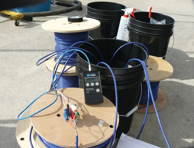
Figure 6-6 Presoaking the Vibrating Wire Transducers
Soak all of the VWTs for about 30 minutes, in either the borehole, or in a bucket of water at the same temperature as the borehole water. Once the VWT has stabilized, lift the VWT just out of the water and record the measured transducer temperature and vibration reading. Record this value on the Installation Log as the VWT’s ‘zero value’.
Compare this ‘zero value’ to the ‘Factory Zero Reading’ on the Calibration Report. These values should not differ by more than 0.1% of full scale. Remember that pressure varies with elevation (your site vs. factory calibration location), temperature, and barometric pressure.
The ‘zero value’ is used to subtract from all future pressure/head readings to calculate final depth to water measurements. See Appendix III for a sample depth to water calculation.
Uncoil the VWT’s cable out to its full length. Push the 3/8″ SS compression fitting with attached VWT onto the Port Stem. Using the 11/16″ and 5/8″ wrenches, tighten the two compression fitting nuts onto the Port Stem by 1 and 1/4 turns.
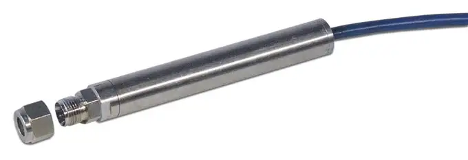
Note:
Record the VWT ‘zero value’ on the Installation Log. It is needed to benchmark against all future readings.
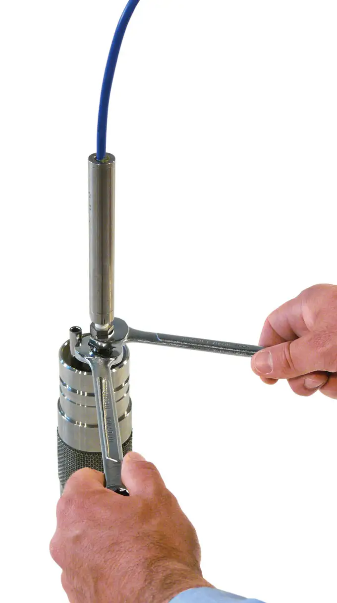
Figure 6-8 Tightening Vibrating Wire Pressure Transducer To Sampling Port
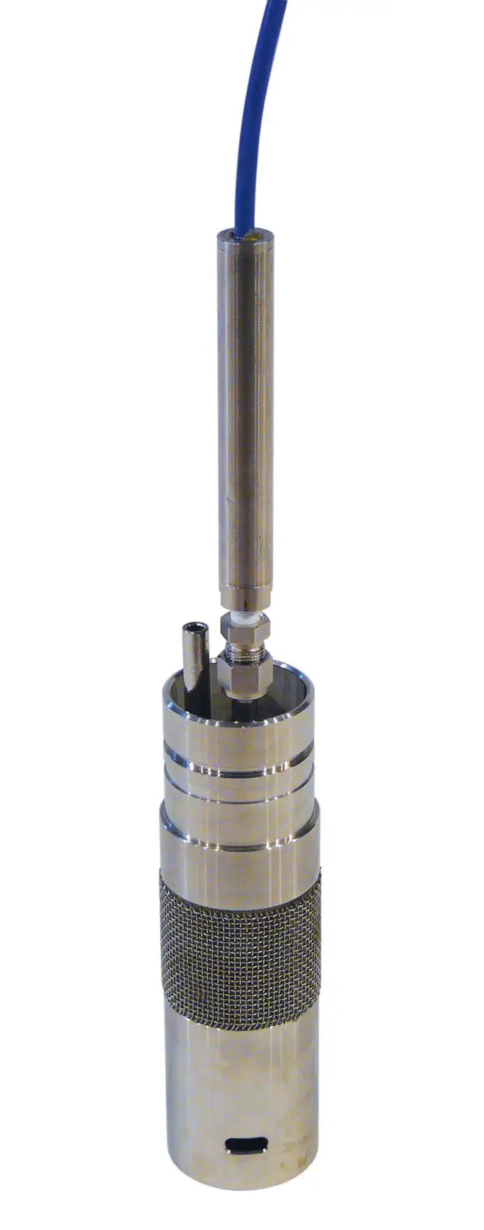
Figure 6 9 Vibrating Wire Pressure Transducer Connected To Sampling Port
6.3 Attaching a Pump (Bladder or Double Valve)
Tools and accessories required: tubing cutter, Oetiker pliers, Oetiker clamps, sand paper, 4″ (10 cm) of 1/2″OD x 3/8″ID tubing, black electrical tape, rod/broom handle.
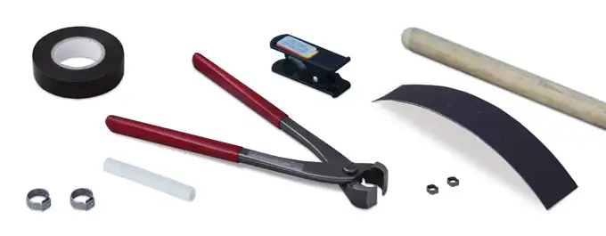
Figure 6-10 Tools and Accessories Required
There are two stems on each pump. The shorter stem is the sample stem, which the sample line (white/natural) will be connected to. The longer stem is the drive gas stem, which the drive line will be connected to. Depending on whether you use LDPE or Teflon-lined, the drive line may be red colored or white/natural, respectively.
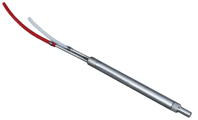
Figure 6-11 5/8″x6″ Double Valve Pump
Beginning with the deepest Port (Port 1), stand at the borehole holding the spool of tubing. A broom handle or equivalent pole works well to hold the spool.
Identify/label the end of this tubing by wrapping a 1″ (25 mm) piece of black electrical tape around the tubing to form a ‘black band’. Let each band represent the Port number. Here, one band of the tape on the tubing end will represent that this tubing will be connected to Port 1. If using Teflon tubing, use a different colour tape to represent the drive line tubing.
A second person will ‘walk’ the end of the labelled tubing to the measured reference mark. Once the tubing end is pulled to this reference mark. Cut the tubing at the spool.
At the next Port, roll off the tubing to the end of the previous cut tubing length, and cut at this reference mark. Use this reference for the remaining Ports, so as more Ports are added, the tubing and cable ends will meet at the same point. Remember to label each length of tubing as you progress.
Note:
Use the black tape to wrap the number of bands corresponding to the Port number around the tubing end (i.e. 1 band of black tape represents Port 1).
Make a clean fresh cut to both tubing ends at the borehole. Place one small double ear Oetiker clamp over each pump stem. Wrap a small piece of sandpaper around the tubing for ‘traction’ and push the sample tubing over the shorter pump stem. Use the sandpaper to help push the drive tubing over the longer pump stem. If you are using Teflon-lined tubing, be sure to check that the Teflon lining has not become separated from the tubing while pushing it onto the pump stem. If you see a ‘bubble’ through the tubing, pull it off the stem, make a fresh cut, and restart this step.
Note:
If you are using Teflon-lined tubing, be careful not to allow the Teflon lining to become separated and cause a visible ‘bubble’ at the Port Stem.
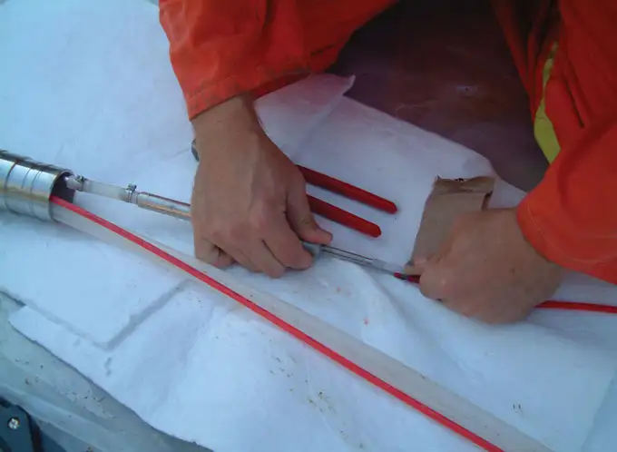
Figure 6-12 Using Sand Paper to Push Tubing onto Pump Stem
Using the Oetiker pliers, incrementally crimp both ears on each clamp. Alternate from one ear to the other, slowly pinching the ears closed. Repeat this cycle 2 or 3 times to achieve a proper crimp. Once the clamp is closed properly you should not be able to see light through the ears of the clamp.
Cut a piece of 1/2″OD x 3/8″ID tubing about 4″ (100 mm) long. Push this onto the Port Stem by about 2″ (50 mm). Using the Oetiker pliers, crimp a #14 Oetiker clamp over the tubing, attaching it to the Port Stem.
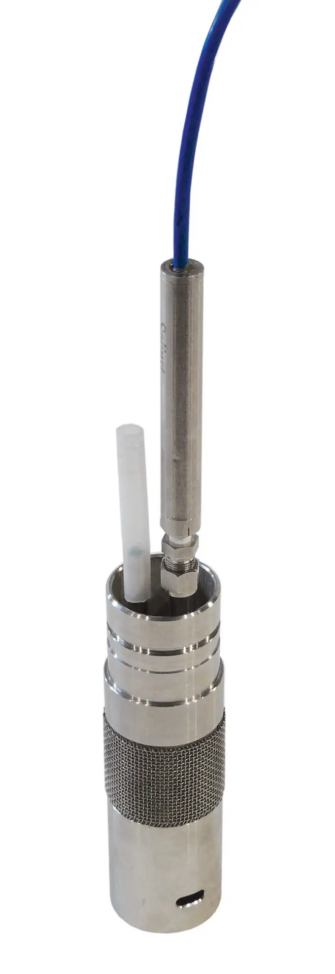
Figure 6-13 Tubing Attached to Port Stem
Place another #14 Oetiker clamp over the open 1/2″OD x 3/8″ID tubing end. Push the pump intake into the tubing end. You will notice that the pump intake is recessed to receive the Oetiker clamp. Crimp the clamp to the pump.
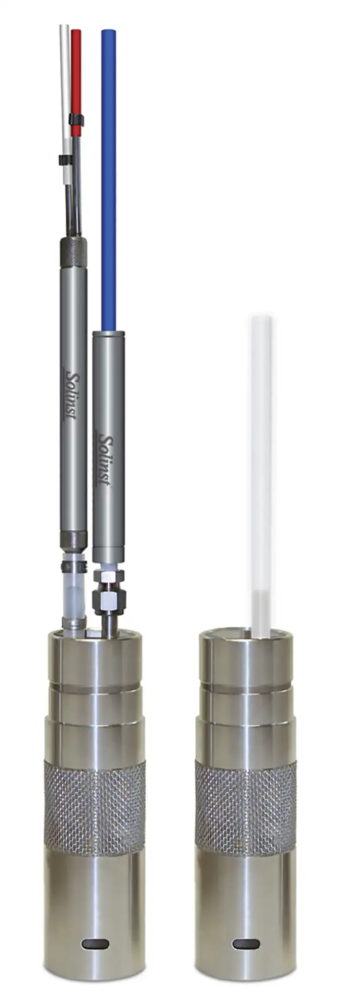
Figure 6-14 Pump Connected to Port Stem

