solinst flute transmissivity profiling

Model 405 Reverse Head Profile

solinst flute

Reverse Head Profile

The Reverse Head Profile is a technique developed by Solinst Flute for measuring the vertical head distribution in a borehole after completion of a Flute Transmissivity profile.

How does the Reverse Head Profile work? 

The method involves the inversion (removal) of the blank liner in a stepwise fashion after the completion of a transmissivity profile. The blank liner is stopped between flow zones of interest as identified by the transmissivity profile. 

As the blank liner is inverted from the well, it uncovers discrete borehole intervals of interest that were sealed during the Transmissivity profile. A pressure transducer located beneath the liner in the borehole records the new steady state borehole equilibrium pressure, Bhi, after each interval is uncovered. As we already know the transmissivity of each interval and the previous steady state borehole equilibrium pressure, we can calculate the contribution of the newly uncovered borehole interval by using each new “blended head” beneath the liner and writing the flow equations for each increment that has been uncovered. 

We define the net flow into and out of the hole to be zero, and using the transmissivity, Ti, measured for each increment in the hole, one has only the formation head, FH as an unknown for each newly exposed interval of the hole.

For the first open borehole interval beneath the liner:

T1(Bh1-FH1) = 0

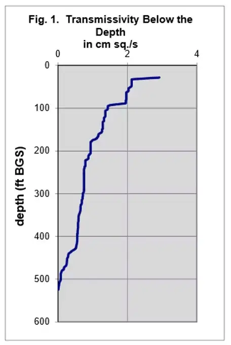
Hence the formation head, FH1, equals the blended head, Bh1, in the borehole. The transmissivity for each interval, Ti, is obtained from the continuous transmissivity integral (Fig. 1). 

Upon inverting the liner to uncover a second increment of the borehole:

T1(Bh2-FH1) + T2(Bh2-FH2) = 0

Solving for FH2, 

FH2= [ T1(Bh2-FH1)+ T2 Bh2 ]/T2

Note:  

For each new position, a new blended head, Bhi, is measured.

Solving for the formation head each time the liner is inverted allows theoretical determination of the head distribution in the formation while removing the same liner that was used to measure the transmissivity and to seal the borehole. 

The equation for solution of the formation head of the current interval, i, is:

FHi = [ T1(Bhi-FH1) + T2(Bhi-FH2) + ……. +Ti Bhi  ]/Ti

Where Ti is the transmissivity of the ith interval in the hole determined from the liner continuous transmissivity profile, FHi is the calculated formation head of the ith interval, and Bhi is the blended head measured in the borehole after each new ith interval is uncovered. Watching the transducer measurement beneath the liner allows one to judge when a steady-state head has been achieved beneath the liner.

figure 1 continuous transmissivity integral

Figure 1. Continuous Transmissivity Integral

Reverse Head Profile Results

comparison of rhp to measured head profile on same day

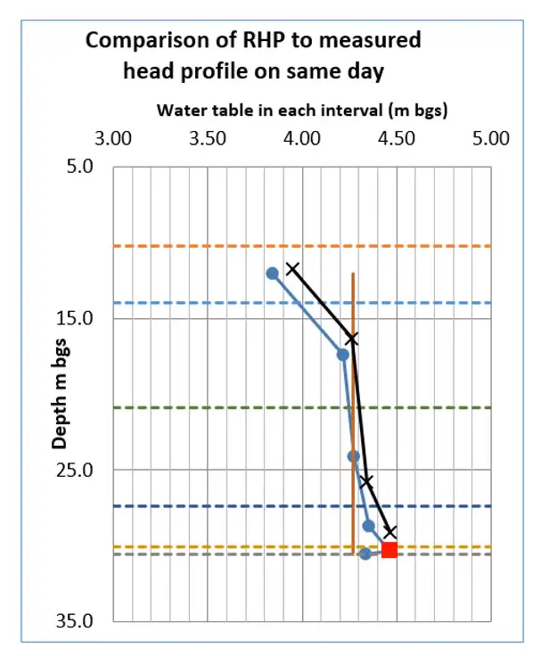
Figure 2. Two Reverse Head Profiles conducted for a 30-Meter Borehole. The blue dots were measured from the 1st RHP values, while the black dots were measured during the 2nd RHP. Note that the vertical red line is the original blended head in the borehole and the red plot point at 30-Meters BGS denotes a measurement taken in a very low transmissive zone and therefore is a less reliable head calculation. 

Related Products

ソリンスト モデル703 ウォータールー エミッター バイオレメディエーション装置

強化されたバイオレメディエーション

について ウォータールー エミッター は、汚染された地下水のバイオレメディエーション用に設計された、シンプルで低コストの装置です。酸素やその他の添加剤を、制御された均一な方法でシリコンまたはLDPEチューブを通して拡散させることができます。MTBEやBTEXの好気性バイオレメディエーションに最適で、メンテナンスは最小限で済みます。

ソリンスト 408M マイクロダブルバルブポンプ

3/8インチ径フレキシブル空圧ポンプ

について マイクロダブルバルブポンプ は、驚くほど小型でフレキシブルな設計です。直径3/8インチ(10mm)で、CMTシステムのチャンネルから地下水をサンプリングするのに十分な大きさです。

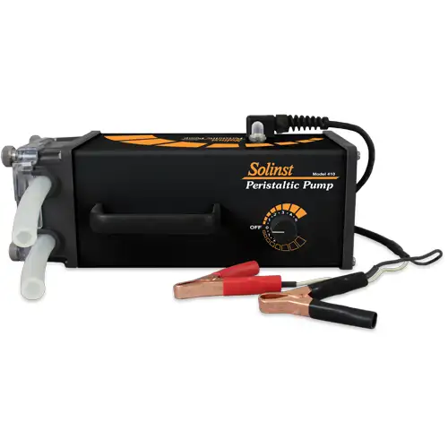
ソリンスモデル410ペリスタポンプ

堅牢なペリスタポンプ

小型、軽量、耐水性のソリンスト蠕動ポンプは、現場での使用に適しています。簡単にアクセスできる1つのコントロールで、様々な速度と可逆流が可能。浅い水や蒸気のサンプリングに最適。

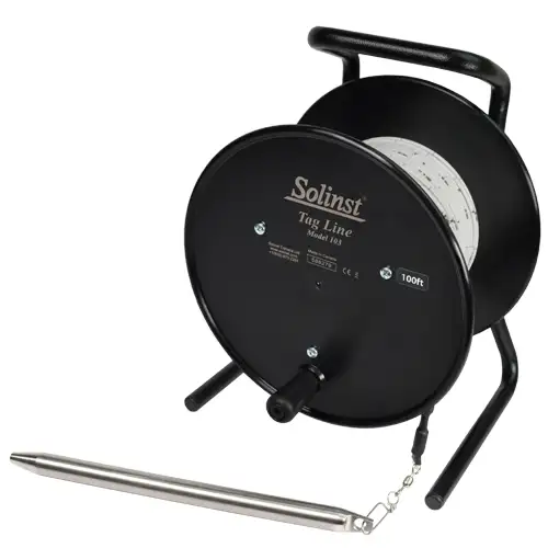
solinst model 103 tag line  for accurate pump and bailer deployments and accurate measuring of backfill layers during well construction

Tag Line – Rugged, Simple, Convenient

The Tag Line uses a weight attached to laser marked cable, mounted on a sturdy reel. Convenient for measuring depths during monitoring well construction.