Model 405 Transmissivity Profiling
Water Quality Probes
Solinst Eureka, a global leader in the design and manufacture of multiparameter water quality sondes.
Solinst Field Services
Safeguard your project’s success and mitigate any potential for downtime or additional costs.

Transmissivity Profiling
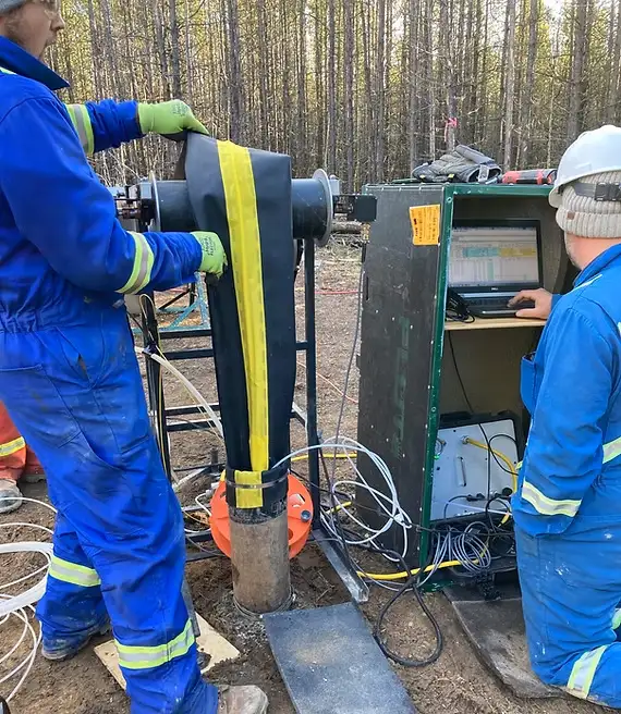
Flute Transmissivity profiles quickly measure all significant flow paths in a borehole with 6 to 12″ resolution in as little as a few hours
How Does it Work?
As a blank liner is installed and everts down the borehole, the water in the borehole is forced into the formation by whatever flow paths are available (e.g. fractures, permeable beds, solution channels, etc.). Figure 1 is a drawing of a simple everting liner with three additional features, (1) The Flute Profiler at the wellhead which measures the liner velocity and additional parameters which can influence the velocity of the liner descent, (2) the pressure transducer measures the excess head in the liner which is driving the liner down the hole, and (3) a pressure transducer measuring the head beneath the liner. From these features, all factors controlling the eversion rate of the liner are monitored.
Measuring the Flow Paths from Boreholes
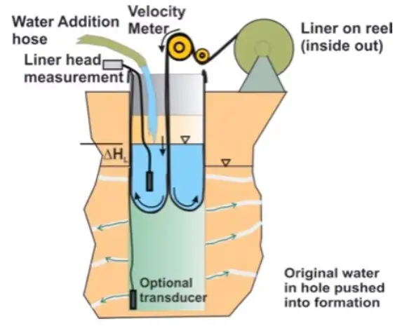
Figure 1. Transmissivity Profiling Setup
The liner descent rate (measured by the Flute Profiler) is therefore controlled by the rate at which water can flow from the hole via those flow paths.
The everting liner is somewhat like a perfectly fitting piston sliding down the hole, except the liner doesn’t slide in the hole, it grows in length at the bottom end of the dilated liner at the “eversion point” as we call it. As the liner everts, it covers the flow paths sequentially.
When the liner begins its descent in the hole, all of the flow paths are open and the descent rate is at its highest. As the liner seals off flow paths, the rate that the borehole water can be displaced out of the borehole decreases and therefore, the liner descent rate decreases as well.
A monotonically fit velocity profile is produced that measures changes in liner descent velocity with depth (Figure 2). The velocity multiplied by the borehole cross sectional area (refined by a caliper log) is the flowrate of the borehole at each interval (Figure 3).
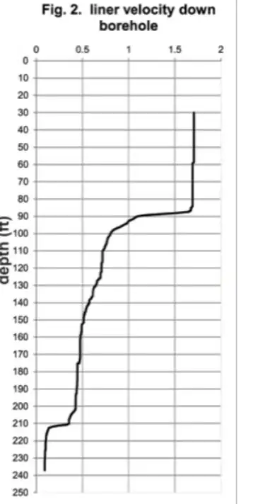
Figure 2. Velocity Profile
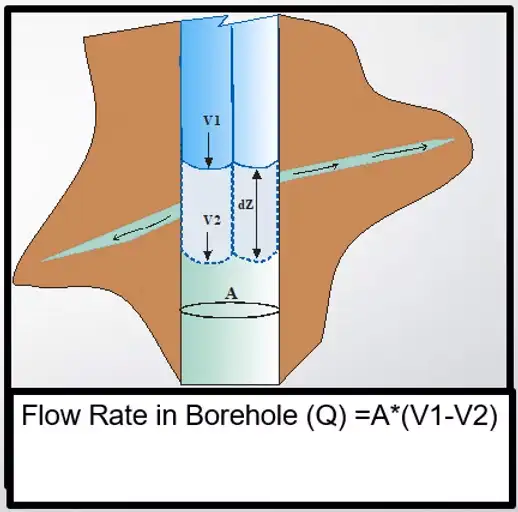
Figure 3. Calculation of the flowrate Q
from the velocity change of the liner
At the start of the profile, the flowrate calculated is of the entire borehole. As the liner seals off flow paths, the borehole flowrate is reduced. The depths in the borehole, which exhibit a decrease in flowrate, identify the location of flow paths and the magnitude of the change is the measure of the flow rate. From the flow rate profile, one can calculate a transmissivity profile for the borehole using the Thiem equation (Figure 4).
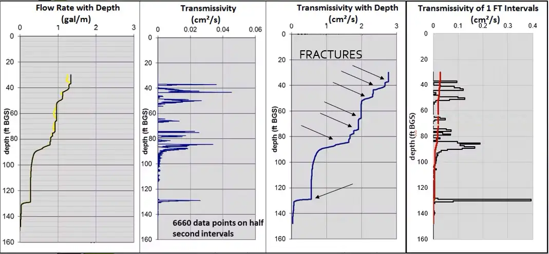
Figure 4. Flow Rate Profile and Transmissivity Profiles
Flute has performed hundreds of these profiles in boreholes to depths of 1000 feet. These boreholes were 3″ to 12″ in diameter. Publications and professional papers comparing the results to straddle packers can be downloaded on our publications page.
In most cases, the Flute Transmissivity Profiler™ can map all of the significant flow paths in the hole in a few hours (10 percent of the time required to do the same mapping with a straddle packer). Furthermore, the detail (6″ to 12″ resolution) in the Flute Profiler measurement is not even possible with straddle packers. The direct measurement of the flow paths with the Profiler may also reduce the need for those geophysical measurements which are used to deduce possible flow path locations in a borehole. Another advantage is that the blank liner is often installed to seal the hole against vertical contaminant migration.
When used in conjuncture with the Flute FACT method, the contaminant distribution can also be mapped using the same blank liner (Figure 5). This data can be used with the Transmissivity profile to develop a fate/transport CSM as well as design a multi-level sampling system.
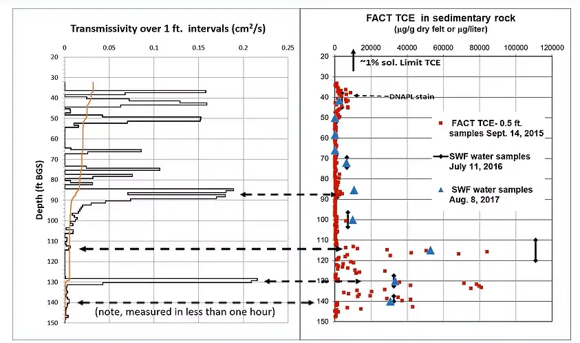
Figure 5. Transmissivity Profile and FACT data. Note the high TCE concentrations at 112′ and 140′ BGS in very low transmissive fractures compared to low TCE concentrations in high flowing fractures at 90′ and 130′. The TCE concentrations at 140′ and 112′ are the same or twice as high, respectively, as the highest flowing fracture in the borehole at 130′ despite the fact that they are two of the lowest flowing fractures in the borehole. This data emphasizes the need for high resolution methods rather than coarse measurements, to assure that all significant contaminant source zones are properly identified during characterization. Water Samples (green diamonds), validate the FACT concentrations.
Given the continuous transmissivity profile, the head profile can be determined by removing the liner in a stepwise fashion using a technique described at head profile.
Related Products
Enhanced Bioremediation
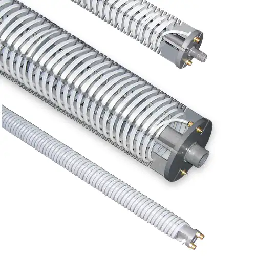
The Waterloo Emitter™is a simple, low cost device designed for the bioremediation of contaminated groundwater. It enables oxygen or other amendments to diffuse through silicone or LDPE tubing in a controlled, uniform manner. Ideal for aerobic bioremediation of MTBE and BTEX, with minimal maintenance required.
3/8" Diameter Flexible Pneumatic Pump
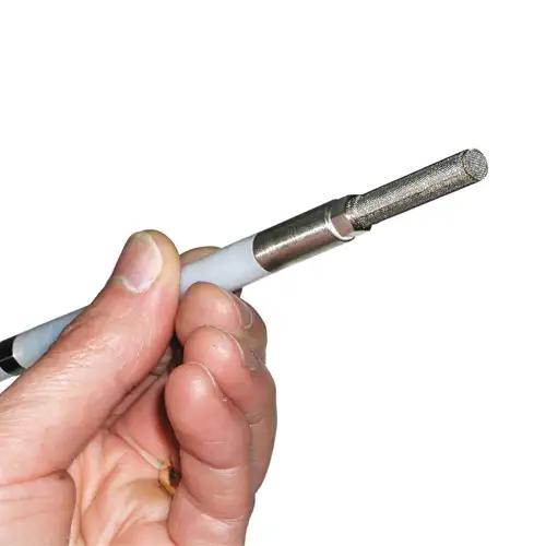
The Micro Double Valve Pump has a remarkably small and flexible design. At 3/8" (10 mm) diameter it is small enough to sample groundwater from channels of a CMT System.
Rugged Peristaltic Pump
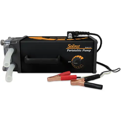
Compact, lightweight, and water-resistant, the Solinst Peristaltic Pump is designed for field use. One easy-access control allows various speeds and reversible flow. Ideal for shallow water and vapor sampling.
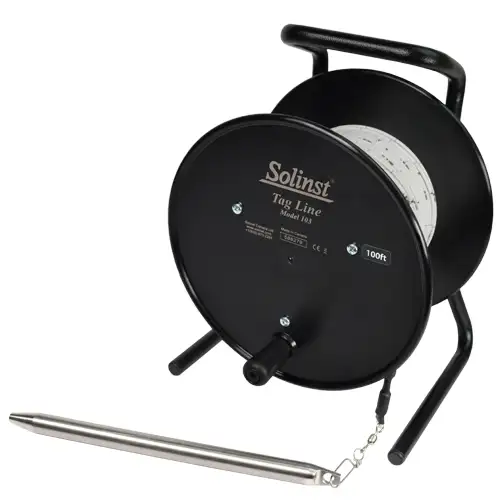
Tag Line - Rugged, Simple, Convenient
The Tag Line uses a weight attached to laser marked cable, mounted on a sturdy reel. Convenient for measuring depths during monitoring well construction.

