Model 405 Reverse Head Profile
Water Quality Probes
Solinst Eureka, a global leader in the design and manufacture of multiparameter water quality sondes.
Solinst Field Services
Safeguard your project’s success and mitigate any potential for downtime or additional costs.

Reverse Head Profile
The Reverse Head Profile is a technique developed by Solinst Flute for measuring the vertical head distribution in a borehole after completion of a Flute Transmissivity profile.
How does the Reverse Head Profile work?
The method involves the inversion (removal) of the blank liner in a stepwise fashion after the completion of a transmissivity profile. The blank liner is stopped between flow zones of interest as identified by the transmissivity profile.
As the blank liner is inverted from the well, it uncovers discrete borehole intervals of interest that were sealed during the Transmissivity profile. A pressure transducer located beneath the liner in the borehole records the new steady state borehole equilibrium pressure, Bhi, after each interval is uncovered. As we already know the transmissivity of each interval and the previous steady state borehole equilibrium pressure, we can calculate the contribution of the newly uncovered borehole interval by using each new “blended head” beneath the liner and writing the flow equations for each increment that has been uncovered.
We define the net flow into and out of the hole to be zero, and using the transmissivity, Ti, measured for each increment in the hole, one has only the formation head, FH as an unknown for each newly exposed interval of the hole.
For the first open borehole interval beneath the liner:
T1(Bh1-FH1) = 0
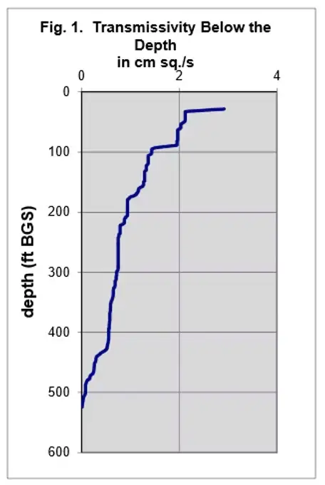
Hence the formation head, FH1, equals the blended head, Bh1, in the borehole. The transmissivity for each interval, Ti, is obtained from the continuous transmissivity integral (Fig. 1).
Upon inverting the liner to uncover a second increment of the borehole:
T1(Bh2-FH1) + T2(Bh2-FH2) = 0
Solving for FH2,
FH2= [ T1(Bh2-FH1)+ T2 Bh2 ]/T2
Note:
For each new position, a new blended head, Bhi, is measured.
Solving for the formation head each time the liner is inverted allows theoretical determination of the head distribution in the formation while removing the same liner that was used to measure the transmissivity and to seal the borehole.
The equation for solution of the formation head of the current interval, i, is:
FHi = [ T1(Bhi-FH1) + T2(Bhi-FH2) + ……. +Ti Bhi ]/Ti
Where Ti is the transmissivity of the ith interval in the hole determined from the liner continuous transmissivity profile, FHi is the calculated formation head of the ith interval, and Bhi is the blended head measured in the borehole after each new ith interval is uncovered. Watching the transducer measurement beneath the liner allows one to judge when a steady-state head has been achieved beneath the liner.
Reverse Head Profile Results
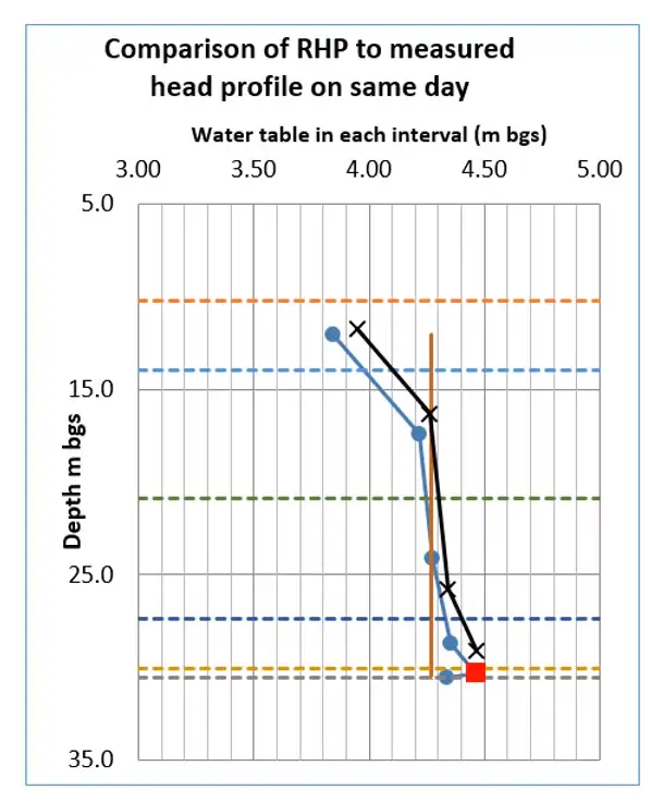
Figure 2. Two Reverse Head Profiles conducted for a 30-Meter Borehole. The blue dots were measured from the 1st RHP values, while the black dots were measured during the 2nd RHP. Note that the vertical red line is the original blended head in the borehole and the red plot point at 30-Meters BGS denotes a measurement taken in a very low transmissive zone and therefore is a less reliable head calculation.
Related Products
Enhanced Bioremediation
The Waterloo Emitter™is a simple, low cost device designed for the bioremediation of contaminated groundwater. It enables oxygen or other amendments to diffuse through silicone or LDPE tubing in a controlled, uniform manner. Ideal for aerobic bioremediation of MTBE and BTEX, with minimal maintenance required.
3/8" Diameter Flexible Pneumatic Pump
The Micro Double Valve Pump has a remarkably small and flexible design. At 3/8" (10 mm) diameter it is small enough to sample groundwater from channels of a CMT System.
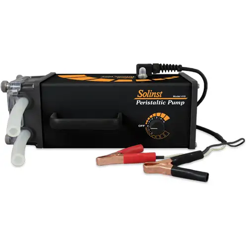
Rugged Peristaltic Pump
Compact, lightweight, and water-resistant, the Solinst Peristaltic Pump is designed for field use. One easy-access control allows various speeds and reversible flow. Ideal for shallow water and vapor sampling.
Tag Line - Rugged, Simple, Convenient
The Tag Line uses a weight attached to laser marked cable, mounted on a sturdy reel. Convenient for measuring depths during monitoring well construction.

