Pre-Installation Requirements
CMT Multilevel System Pre-installation Requirements
Please complete this form to verify that proper consideration has been given to design and borehole specifications for each CMT Multilevel System to be installed. (CMT tubing 1.7” OD, Guide Point Port 1.75” OD, Guide Point Port with Anchor 3.75” OD).
a) Minimum information required for effective design of the CMT Multilevel System:
Accurate borehole depth _______________________________
Borehole Angle _______________________________
Depth to whichCMT Systemis to be installed _______________________________
Borehole geology _______________________________
Drilling Method_______________________________
Casing size (minimum ID) _______________________________
Depth to base of well casing _______________________________
Number of Monitoring Zones _______________________________
Approximate Depth toStatic Water Level_______________________________
Expected Maximum Pressure Heads at each Port location _______________________________
Site Conditions (eg. dry field, bush, swamp, paved, etc.) _______________________________
Any special surface requirements for completion of installation (eg. flush mounted, angled, etc) _______________________________
Solinst can assist the client in the component selection for the CMT Multilevel System based on the above requested information, but final design and installation details remain the responsibility of the purchaser.
b) Ensure that these additional items are available on site during installation:
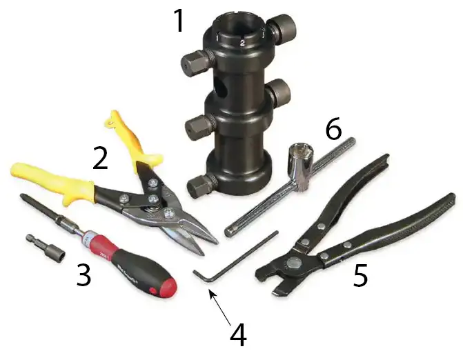
- CMT Installation Toolkit (as shown below)
- Measuring tape
- Hacksaw
- Marking pen or wax pencil
- Model 102 or 102M Water Level Meters
- Model 103 Tag line for checking backfill depths
- At least two client representatives to supervise and assist with installation.
- Support stand (if purchased separately)
- Adjustable wrench

Hand Tools for CMT Multilevel System Assembly
- Port Cutting Guide
(7 Channel Part Number 106850)
(3 Channel Part Number 107239) - 403 Sheet Metal Shears – 10″
Part Number 107983 - 403 Torque Tool Assembly – 12.5 in lbs
Part Number 107255 - 1/8″ Allen Wrench
(comes with Port Cutting Guide) - 403 Oetiker LP Pliers
Part Number 100177 - Hex Wrench
(comes with Port Cutting Guide)
