Introduction
Note:
Optional webinar installation training is available. Contact Solinst for details.
Note:
Always follow local health and safety guidelines. Work safely.
The Solinst Model 403 CMT Multilevel monitoring well system represents a revolution in multilevel groundwater monitoring. The CMT System provides the simplicity of a bundle type installation with the benefits of backfilling or sealing around a single tube.
This manual describes the above-ground assembly of CMT wells. This consists of creating intake ports in the various channels at the desired depths, installing water-tight plugs below each intake port, adding mesh screens, sealing the bottom of the tubing, and attaching low-profile borehole centralizers to the tubing. For installations in bedrock or cased 2″ wells, inflatable packers can be attached to the CMT tubing to seal the borehole between the various intake ports.
Note:
Practice making one or two ports in a short section of CMT before starting out on the real thing.
Assembling CMT wells is straightforward and can be performed by either drilling contractors or environmental consultants. The wells can be assembled on site while the borehole is being drilled or off site and then transported to the job location. While the assembly of CMT wells is not difficult, it is important to follow all of the steps described in this manual. It is especially important when creating the monitoring ports to avoid cutting into one of the adjacent channels. Doing so creates a hydraulic connection between the two channels that cannot be repaired. Please read this manual carefully before assembling your first CMT well. In addition we suggest that you practice making one or two ports in a short section of CMT tubing before starting out on the real thing.
If needed, Solinst can provide one-on-one installation training in a number of different ways, such as a classroom setting, outdoors, or a webinar tutorial and presentation. Contact Solinst for details.

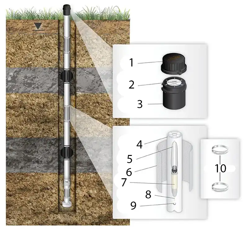
Figure 1 – Solinst CMT Multilevel System Components Diagram
- Well Cap
- Numbered Channel
- CMT Wellhead
- Polyethylene CMT Tubing
- Channel Cutout
- Screen
- Plug
- Channel Identifier
- Vent Hole
- Oetiker Clamps
