Installing Narrow CMT Spring Cartridges
Depth Discrete Groundwater Monitoring
Reduce Costs and Field Time
Figure 32 shows all parts required to construct a Bentonite Spring Cartridge.
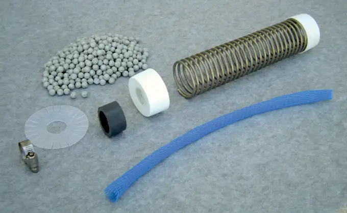
Figure 32 – Narrow Diameter 3 Channel CMT Spring Cartridge Setup
Slide the length of polyethylene mesh over the Feeder Tube. Allow for about 2″ (50 mm) of slack in the mesh at each end. You will need this extra length of mesh later to fold up and over the End Cap. Tuck one end of the mesh into the end of the Feeder Tube and slide an End Cap down and over the plastic mesh, then place the empty SS Spring into this End Cap.
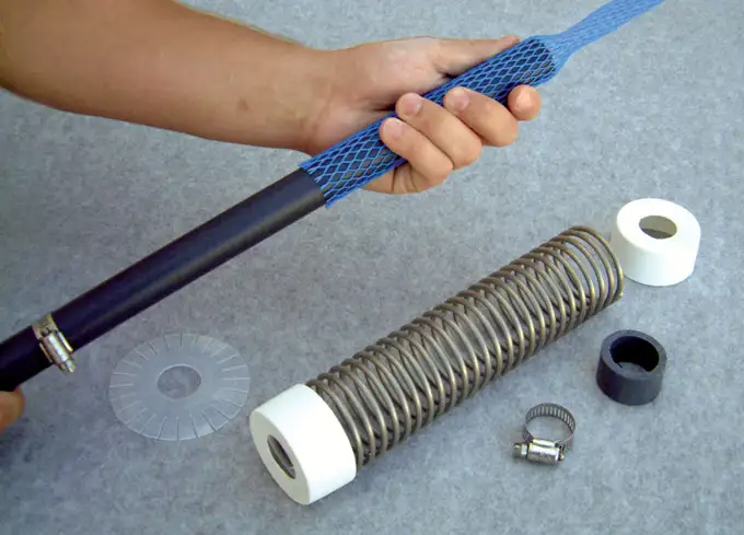
Figure 33 – Installing CMT Multilevel System Spring Cartridge
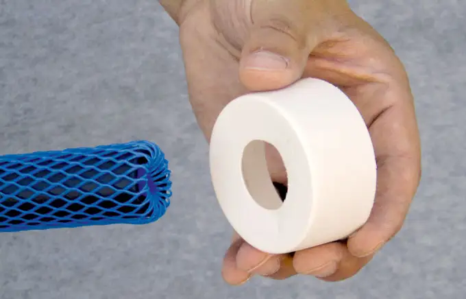
Figure 34 – Installing CMT Multilevel System Spring Cartridge End Cap
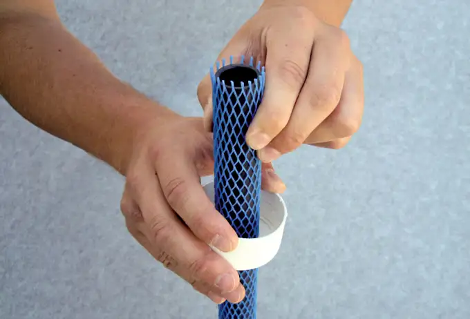
Figure 35 – Installing CMT Multilevel System Spring Cartridge End Cap Over Mesh
By hand (Figure 36) slowly fill the Bentonite Spring Cartridge. Shake the Feeder Tube to ensure an even filling. Do NOT twist the SS Spring. This will cause the spring to lock onto the Feeder Tube. Once filled, remove the Feeder Tube and add the other End Cap to the Cartridge Assembly. Pull the mesh up and over the End Cap at each end.
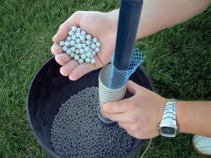
Figure 36 – Pouring Bentonite Pellets into CMT Multilevel System Spring Cartridge
Note:
Remember to slide a Spacer, Separator Disk and Gear Clamp below each Cartridge
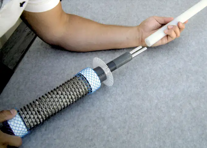
Figure 37 – Slide a Spacer Separator Disk and Gear Clamp below each CMT Multilevel System Cartridge
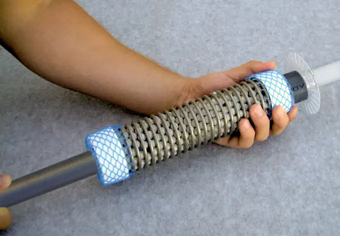
Figure 38 – Complete CMT Multilevel System Spring Cartridge with Bentonite Installed
Note:
If you are installing through 3.25″ diameter “Direct-Push” casing, once the Spring Cartridge is slid into position, cut the blue plastic mesh off of the plastic end caps. This allows the Spring Cartridge to fit inside the casing.
Continue to install the next Bentonite Spring Cartridges until the clay seals above and below the middle port are in place (In our example, above Port 3 as well as below Port 1.)
Then cut, prepare, and install the next ports, as described on Pages 6-9 and/ or install Sand and Bentonite Cartridges as required. Always work from the centre out and complete the CMT System with a Guide Point and Well Head as described on Configuring the Bottom of the CMT Tubing, CMT Placement and Attaching Standard Wellhead.
