Installing Narrow CMT Sand Cartridges
Depth Discrete Groundwater Monitoring
Reduce Costs and Field Time
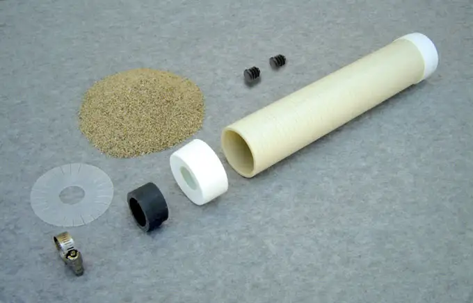
Figure 29 shows everything required to construct a Sand Cartridge; PVC screen, sand, two black plugs (one as spare), two End Caps, Spacer, Separator Disk, and Gear Clamp.

Figure 29 – CMT Multilevel System Sand Cartridge Setup
Note:
Remember to construct the CMT System from the middle port and work outward and towards the top and bottom. BELOW each Cartridge, slide on a Spacer, Separator Disk and Gear Clamp.
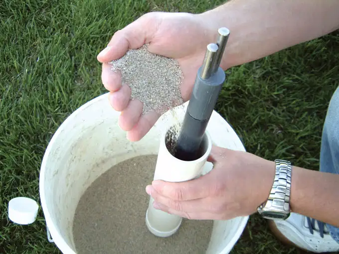
Push an End Cap onto the 2″ (50 mm) diameter screen and push the Feeder Tube all the way through the centre of the PVC screen. By hand, (see Figure 30) slowly add sand to the Sand Cartridge. Do NOT overfill the Sand Cartridge. Leave about 2″ (50 mm) of head space so as to ensure the assembly will slide along the CMT without creating too much friction. Once filled, add the other End Cap to the Sand Cartridge Assembly.
Remember to construct the CMT from the middle (Port 2 in our example) and work outward and towards Ports 1 and 3.

Figure 30 – Pouring Sand Into CMT Multilevel System Sand Cartridge
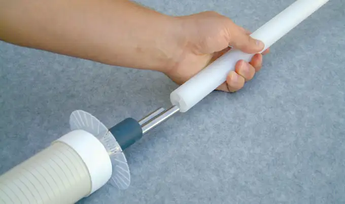
Insert the Feeder Tube and Key into the end of the CMT tubing. To prevent sand infiltration while placing the Sand Cartridge, use a black plug to block the vent hole. Slide the Sand Cartridge along the CMT over the screened port, and into position at Port 2 (see Figure 31). Do not forget to slide on a Gear Clamp, Separator Disk and Spacer. Use the supplied Torque Driver (12.5 in/lbs) and tighten the Gear Clamps.
Note:
Push a small black plastic plug into the vent hole below the port, to prevent sand draining out of the Sand Cartridge.

Figure 31
