Cutting the Ports and Vent Hole
Step 8) Install the Port Cutting Guide
Slide the Port Cutting Guide over the CMT tubing down to Port 1. Align the notch stamped “1” on the Port Cutting Guide with the line you drew along the Channel 1 identifier. Position the Port Cutting Guide so that the depth mark “+” (indicating the centre of the Port) is visible in the window in the center of the Port Cutting Guide (Figure 6). Secure the Port Cutting Guide to the CMT tubing by tightening the knurled Locking Bolts on the underside of the guide (Figure 7). Tighten the bolts, by hand only, to prevent the Port Cutting Guide from moving.
Note:
When using the Port Cutting Guide, ensure that the three cutting bolts are located below the number 1 on the front of the Guide. The two locking bolts are on the back of the Port Cutting Guide.
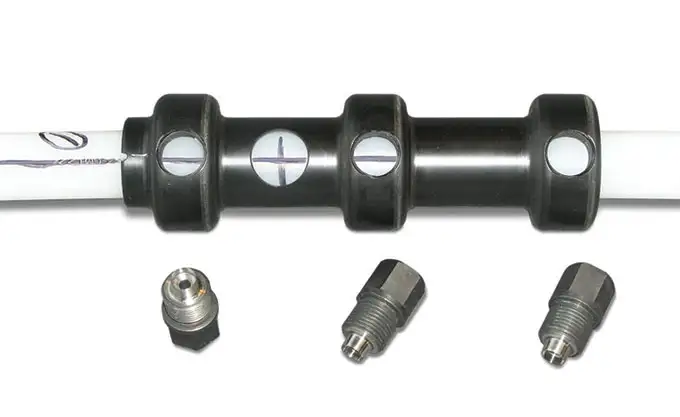
Figure 6 – 3 Channel CMT Port Cutting Guide
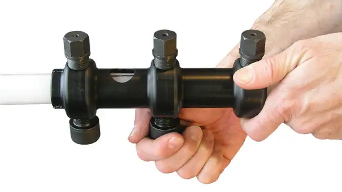
Figure 7 – Using 3 Channel CMT Port Cutting Guide
Step 9) Use Cutting Bolts to Cut Holes
Next, make three holes, as described below into Channel 1 using the cutting bolts screwed into the Port Cutting Guide. Do not rush when screwing the cutting bolts into the Port Cutting Guide. Ensure the bolts are properly lined up with the holes in the Port Cutting Guide so that cross threading does not occur.
Note:
Do not rush when screwing the cutting bolts into the Port Cutting Guide. Ensure the bolts are properly lined up with the holes in the Port Cutting Guide so that cross threading does not occur.
Start by threading a cutting bolt into one of the holes located on the same side as the window. Use the hex wrench to tighten the Cutting Bolt. Tighten the bolt a few revolutions, then loosen it one revolution. Continue doing this until the Cutting Bolt “bottoms out” (Figure 8). Remove the Cutting Bolt. There should be a plastic disk inside of the cutting bolt. If there isn’t, re-insert the cutting bolt and repeat the cutting process (make sure that the knurled Locking Bolts are tight). Push out the piece of plastic from the inside of the Cutting Bolt by inserting an Allen wrench through the small hole drilled in the head of the Cutting Bolt (Figure 9 ). Repeat this process to cut all three holes. The two upper holes, on either side of the depth marked “+”, will provide the port plug access and the lowest hole is the vent hole (Figure 10).
Note:
For easy effective cutting, advance the cutter bolt in alternating increments of ~1.5 turns clockwise, and then 0.5 turn counter-clockwise, repeatedly.
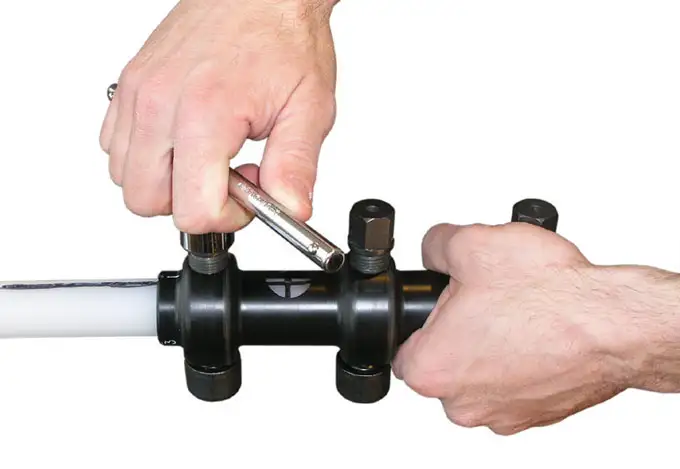
Figure 8 – Tightening the CMT 3 Channel Port Cutting Guide
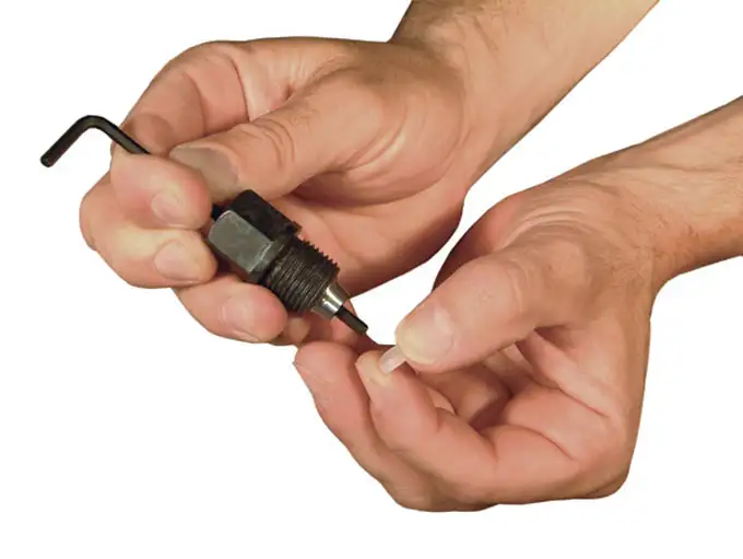
Figure 9 – Removing CMT LDPE Plastic Plug from Port Cutting Guide

Figure 10 – 3 Channel CMT Port Cutting Hole Setup
Note:
If installing numerous systems, spare cutting bolts can be ordered, as they may become dull after repeated use. It is recommended to order an extra bolt per 10 ports constructed.
Step 10) Cut Panel Between Upper Two Port Holes
Loosen the cutting tool and move it “down” the CMT and out of the way. Next, use the snips as shown in Figure 11 to cut out the panel of plastic between the upper two port holes. Do this carefully and keep the snips parallel to the channel side wall to avoid cutting into the walls separating Channel 1 from Channels 2 and 3. Make the opening as large as possible to facilitate the insertion of the expansion plug as described in the next step.
Note:
The two upper holes allow you to use snips to cut out a panel of plastic between them, creating a 3″ long opening in Channel 1.
The bottom hole is a vent hole. This vent hole is needed to allow air to escape from the channel beneath the monitoring port when the CMT tubing is inserted into the waterfilled borehole during well installation.
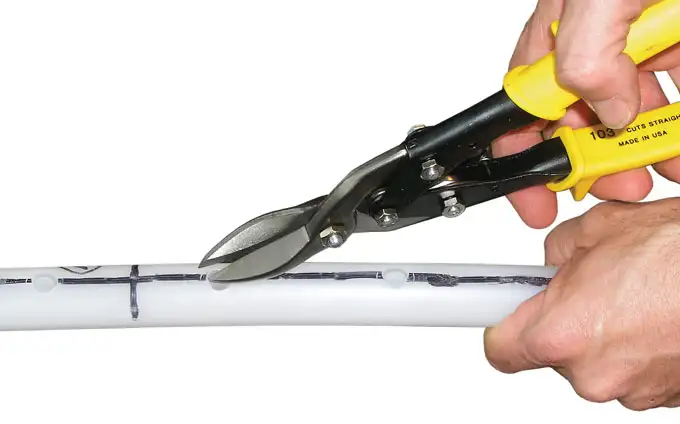
Figure 11 – Cutting Sampling Port Area for 3 Channel CMT Multilevel System
Note:
The vent hole does not allow cross connection with other monitoring zones because the bottom of the channel is sealed with a watertight plug.
Step 11) Insert Expansion Plug
Insert an expansion plug through the opening (Figure 12) so that it seals Channel 1 below the monitoring port and above the vent hole. If necessary, use the torque driver to gently push the plug into place (Figure 13). Use the snips to trim the port opening if you have difficulty inserting the plug. Tighten the plug to a torque of 12.5 inch-pounds using the supplied torque driver.
Note:
When installing the exansion plug, temperature of the CMT should be between -15ºC and 35ºC. If air temperature is above 35ºC, use cold water to cool down the tubing at the port before installing the expansion plug.
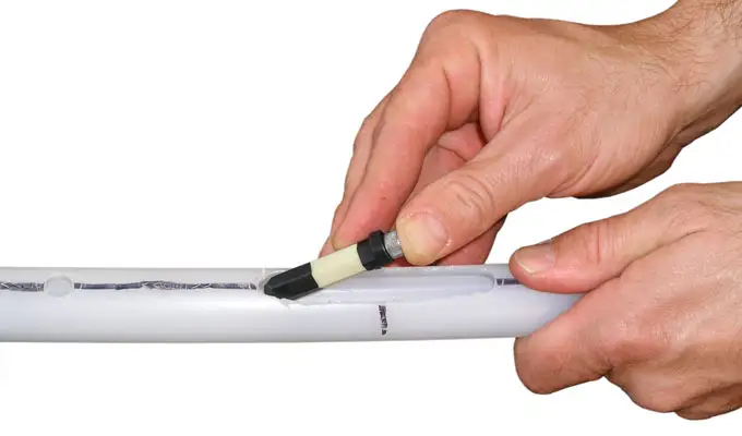
Figure 12 – Insert CMT Hex Channel Hex Port Plug
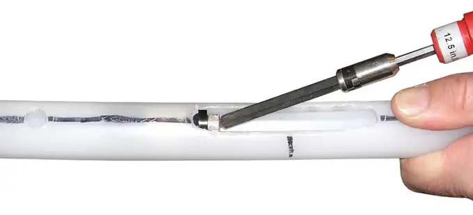
Figure 13 – Tightening Hexagon Sampling Plug for Narrow 3 Channel CMT System
Note:
If you are installing Sand or Bentonite Cartridges, please see Cartridge Installation section before proceeding. Spring Cartridges must be placed on the tubing before Port Screens are installed.
Step 12) Install the Well Screen
The last step in making the Channel 1 port consists of wrapping the stainless steel mesh around the port, forming a well screen over the opening. Center the mesh over the port opening and wrap it tightly around the CMT tubing (Figure 14). Use the low profile Oetiker clamps and pliers to firmly secure the mesh to the tubing. Use three clamps for each monitoring port (Figure 16). Construction of Port 1 is now finished. You are now ready to make Port number 2.
Note:
Wetting the Oetiker Clamp reduces friction, making installation easier.
Installing Oetiker Clamps
Wrap the Oetiker clamp around the part (eg. screen, centralizer, guide point) you are clamping. Allow the first (closest) retaining hook to pass through the long slot opening. Squeeze the clamp by hand until the retaining hook catches the end of this opening. Figure 15 shows this step. Fit the ‘jaw tips’ of the Oetiker pliers into each of the clamp’s ‘tunnels’. Squeezing/closing the Oetiker pliers simultaneously draws the two tunnels together. With the two tunnels drawn together, push down on the tail of the clamp, so that the furthest retaining hook passes through the last slot. Now release the pliers so that the retaining hook catches the clamp and holds.
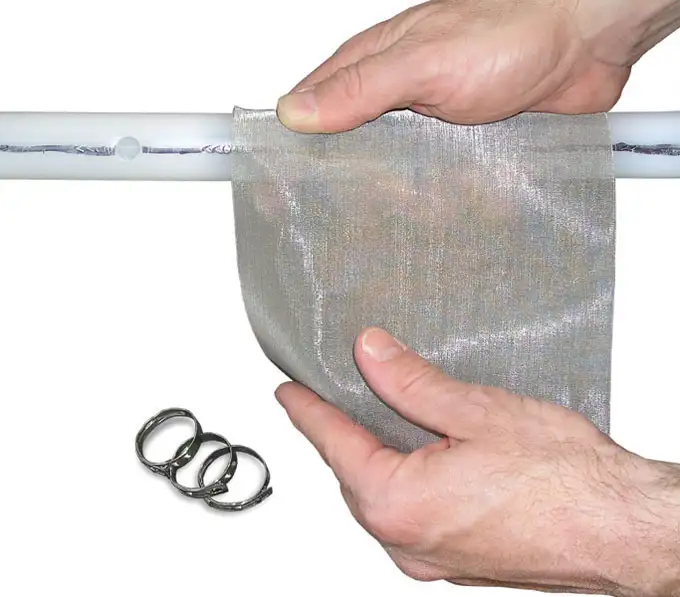
Figure 14 – Wrapping 3 Channel CMT Port with Stainless Steel Mesh
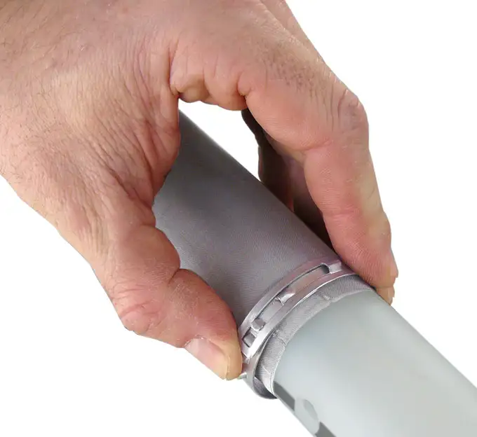
Figure 15 – Wrapping Oetiker Clamp over 3 Channel CMT Multilvel System Stainless Steel Mesh
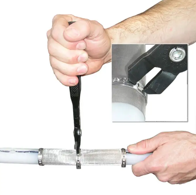
Figure 16 – Tightening Oetiker Clamp over Stainless Steel Mesh Sampling Port
Step 13) Line-up Port Cutting Guide
Slide the Port Cutting Guide “down” to Port 2. Position the Port Cutting Guide exactly as you did for Port 1. The depth mark should be visible in the window of the Port Cutting Guide and the longitudinal Channel 1 identifier should be indexed to the number “1” stamped on the guide (Figure 17). Now, rotate the Port Cutting Guide (without moving its position along the CMT tubing) so that the “<< CMT >>” identifier is now indexed to the number “2” stamped on the guide (Figure 18).
Note:
To avoid installing ports in the wrong channels, start by positioning the Port Cutting Guide so that the depth mark is visible in the window, then rotate the guide so that the appropriate number (corresponding to the port number) is indexed against the line you drew earlier along the <<CMT>> Channel 1 identifier. This step is very important.
This positions the Port Cutting Guide so that the cutting bolts will cut holes only into Channel 2. Secure the Port Cutting Guide using the knurled Locking Bolts as before. Cut the two port holes and one vent hole into Channel 2. Next, loosen the cutting tool and slide it “down” the tubing out of the way.
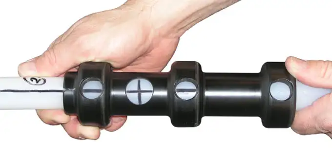
Figure 17 – Aligning 3 Channel CMT Port Cutting Guide at Desired Sampling Zone
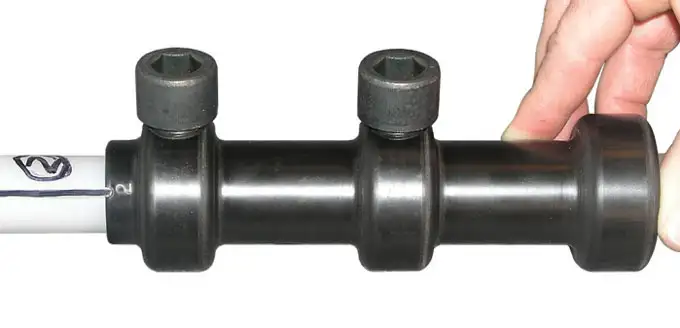
Figure 18 – Aligning 3 Channel CMT Port Cutting Guide
to the correct CMT Multilevel System Channel using the top of the port cutting guide
Step 14) Create Port 2 Opening
Snip away the panel of plastic between the upper two holes, creating an opening for Port 2.
Step 15) Finish Constructing Port 2
Insert an expansion plug though the opening, positioning it below the monitoring port, and tighten it to 12.5 inch-pounds as before. Finally, wrap a piece of stainless steel mesh around the opening and secure it with three stainless steel clamps. You have now finished constructing Port 2.
Step 16) Construct Port 3
Continue the steps described above for Ports 3.
