401 Waterloo System: Assembly Manual Appendix
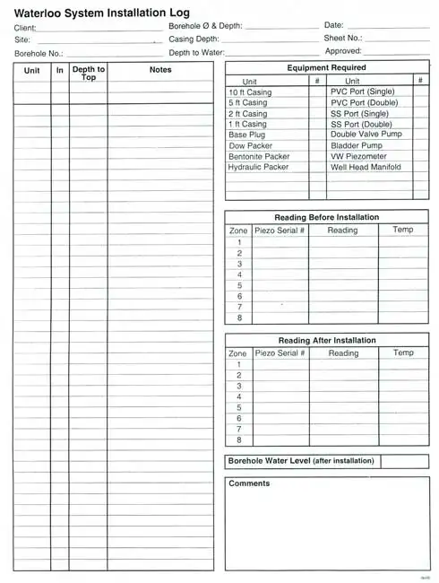
Waterloo System Installation Field Log

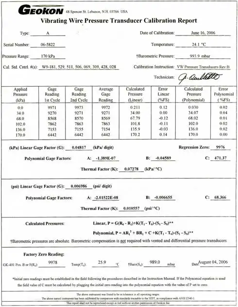
Vibrating Wire Transducer Calibration Report

Sample Vibrating Wire Calculation
Sample Calculation
Converting a VWT reading from the GK-404 to a depth to water
In our example, let’s assume the VWT is connected to a monitoring port that is located at a depth of 100 ft (30.48 m) below ground surface.
From the GK-404 readout:
Zero Reading (pre installation) of VWT: 9978 digits
Submerged Reading of VWT: 7978 digits
Difference between Zero Reading & Submerged Reading: 2000 digits
From the “Vibrating Wire Pressure Transducer Calibration Report”
(sample in Appendix III), locate the “Linear Gage Factor” for each specific transducer serial number. In our example:

To calculate the pressure head (psi or kPa) on the VWT, multiply the appropriate “Linear Gage Factor”, by the difference between the zero reading and submerged reading. From our example:
0.006986 (psi/digit) x 2000 digits = 13.972 psi (96.33 kPa)
Therefore, VWT serial number 06-5822 has a pressure head of 13.972 psi (96.33 kPa).
To calculate the depth to water, simply convert psi (kPa) to feet (meters):
13.972 psi x 2.307 foot of head/psi = 32.23 feet of head.
96.33 kPa x 0.1020 meter of head/kPa = 9.826 meters of head
Now subtract the depth to the Port inlet (100ft/30.48m) from the pressure head.
100 ft – 32.23 feet of head = 67.77 ft.
30.48 m – 9.826 meters of head = 20.65 m
Terms and Conditions
for Waterloo or CMT® System Multilevel
Installation Training
An Understanding of Responsibility
Solinst Canada Ltd. (Solinst) offers installation training only, which includes providing verbal and ‘by example’ instruction of proper methods of assembling Waterloo or CMT Multilevel Systems. Actual installation of a Solinst Multilevel System is the sole responsibility of the Customer. Solinst cannot offer guidance, nor recommend the location of a monitoring zone, nor advise on the backfilling of the System to achieve the monitoring zones your site requires.
Based on the information that you provide, Solinst may assist with determining sufficient quantities of components to construct your Multilevel System(s), however Solinst assumes no responsibility for the chemical and physical compatibility of materials, initial design or on- site layout design, in-field design changes, or the condition of the borehole(s).
All equipment received by the client for use in their installations must be inspected upon receipt, and any deficiencies noted and reported to Solinst immediately.
Solinst, at its sole discretion, reserves the right to assess the cause and liability of any System fault or equipment failure at the time of receipt, during assembly, or following installation. If the defect is determined to be caused by inadequate materials or workmanship, excluding actual installation procedures – which are the Customer’s responsibility – Solinst will, at it’s own discretion, replace or refund the cost of the failed component. Solinst is not liable for any contingent costs which may arise from the installation for any reason including the loss of use of any part of the System(s) or borehole(s).
The undersigned understands and accepts the above terms and conditions:
Company: __________________________
Name: _____________________________
Signature: __________________________
Date: ______________________________


