401 Waterloo System: Assembly Manual 4.0 Assembling the System
One person should be assigned as ‘Team Leader’ for the installation. This Team Leader is key in directing and ensuring that the components of the System are installed in the correct sequence. The Team Leader will keep an ‘as built’ record of the Waterloo Multilevel System.
Note:
A System about 100 ft. (30 m) below water will most likely require water added to the casing string during installation in order to counter System buoyancy (see Section 8.0).
When packers are used, the water inside the casing string should not exceed the static water level of the borehole during installation.
Arrange and group all of the equipment for each separate System near the borehole. Inventory and record each piece, as is proposed for the System on the Waterloo System Installation Field Log (see Appendix I for example).
Unpack the (optional) vibrating wire transducers (VWT) and soak them in water. Preferably submerse them in the borehole or in a bucket of water close in temperature to borehole groundwater. These need to stabilize prior to obtaining their individual ‘zero value’ (head/pressure) reading (see Section 6.2).
On the most suitable ground surface, measure off and mark a line out from the borehole 10% longer then the depth to the deepest Port. By example, if the deepest Port is at 100 ft. (30 m), measure off and make a reference mark at 110 ft. (~33 m). This is your initial reference for cutting tubing. If required, unroll a ~3 ft. (1 m) wide length of thin mil plastic (Visqueen) polysheeting to this mark.
If used, uncoil and lay out the support cable. The outstretched cable will likely be about 5 ft. (1.5 m) beyond the length of your plastic and reference mark.
Note:
If not using a support cable, begin with the Base Plug near the borehole, and simply follow the design log to attach the components in sequence.
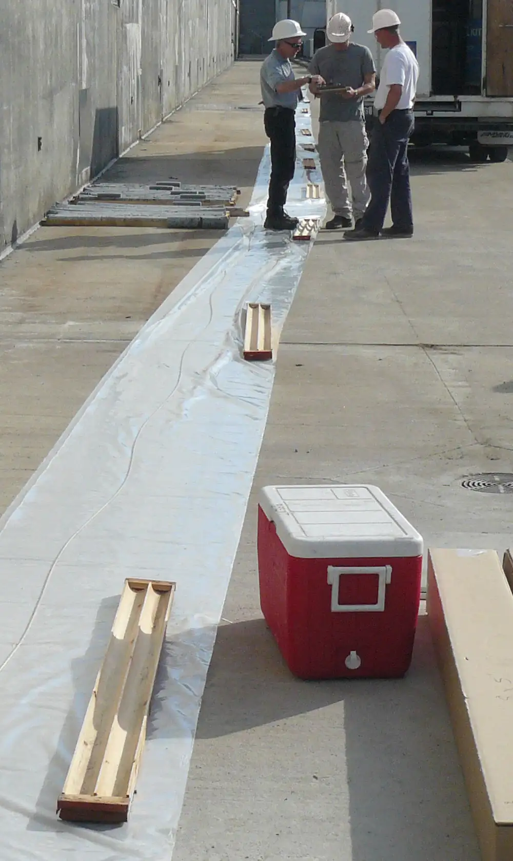
Figure 4-1 Plastic & SS Support Cable Laid Out (Wood core boxes are used here to weigh down plastic)
Note:
See Section 5.0 for joint connection instructions and Section 6.0 for connecting tubing and/or cabling to each Port.
To begin, attach the stainless steel Base Plug to the end of the support cable nearest the borehole. Following the sequence as set in your Installation Log, each component is walked to the far end of the plastic and threaded over the support cable, female joint end first, and walked back to the borehole for connection to the previous component. Section 5.0 discusses how to connect each joint.
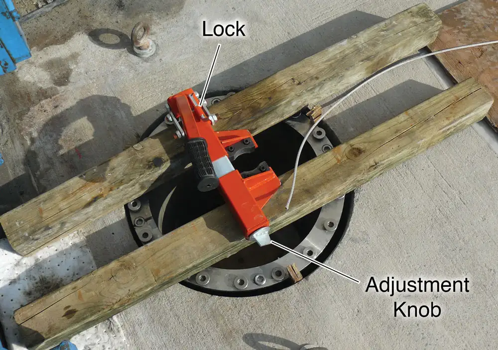
Figure 4-2 An Installation Clamp Over a Borehole
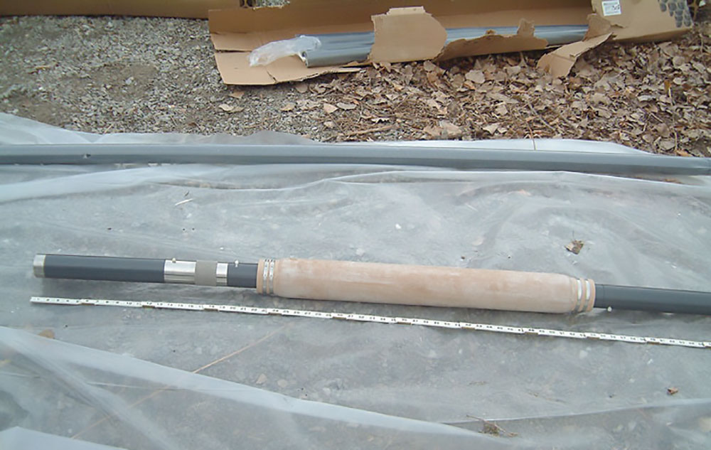
Figure 4-3 A Base Plug, Casing, Port, and Packer Section
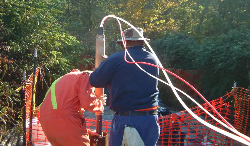
Figure 4-4 Initial Section Being Installed Down-hole
When adding each Port to the sequence you will connect the monitoring tubing and/or transducer or pump to be used at that Port. Each successive component will be threaded over the support cable, as well as the monitoring tubing and cabling as it is added. Section 6.0 discusses Port connections.
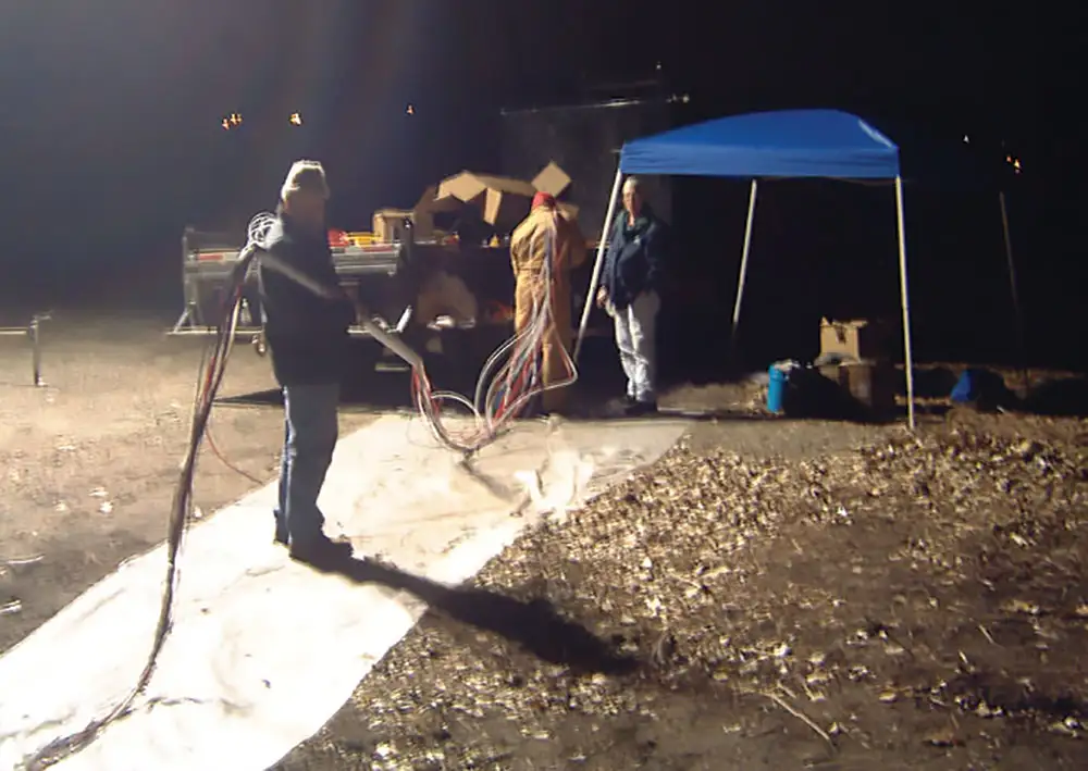
Figure 4-5 Casing Section Being Threaded Over Monitoring Tubing
Once at least 5 ft. (1.5 m) of the System has been assembled, start lowering the System into the borehole. Adjust and lock the installation clamp onto this assembly to hold it in place. The System is now hanging in the borehole and supported by the installation clamp.
Continue to install the Waterloo Multilevel System in the sequence shown in your Log, making each connection as described in the following section. Be sure to record the components as they are assembled over the borehole on the Installation Log (see Appendix I).
Note:
To use the installation clamp, slide the unlocking bar to the unlocked position and open the clamp by lifting the handle. Adjust the width of the jaws via the adjustment knob so the casing is held tightly when the clamp is closed. Return the locking bar to the locked position.

