Attaching the Standard CMT Multilevel Wellhead
Water Quality Probes
Solinst Eureka, a global leader in the design and manufacture of multiparameter water quality sondes.
Solinst Field Services
Safeguard your project’s success and mitigate any potential for downtime or additional costs.
Step 23) Attach the Wellhead
After the well has been built, cut the CMT tubing to the final elevation. You may choose to finish your CMT installation above ground surface. If so, you can leave the CMT stick-up as is and install the standard wellhead register or “house” the CMT inside a cut length of 2″ dia. PVC riser pipe (not supplied).
If housing in a PVC pipe, first slide the PVC pipe over the CMT stick-up, and push below the final elevation of the CMT. Slide the wellhead base over the tubing and onto the PVC pipe. The wellhead base provides a tight friction fit on the PVC pipe.
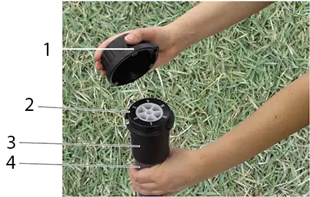
Slide the wellhead register flush with the end of the CMT tubing. Align the stamped number one on the register with the Channel 1 identifier marking on the outside of the tubing. Secure the wellhead to the CMT tubing by tightening the hex screw on the side of the wellhead register using a 1/8″ Allen Key. Bring the PVC pipe up so the register seats in the wellhead base (Figure 24). Grout or cement the PVC pipe in place.
Figure 30
7 Channel Standard Wellhead
(Part Number 110525)
- Well Cap
- Wellhead Register (insert)
- Wellhead Base
- Optional Nominal
2″ OD PVC Casing
(sold elsewhere)

Optional Flow Control Monitoring Assembly
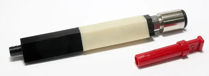
Under flowing artesian conditions or for vapor sampling, the CMT can be fitted with a flow through seal assembly (Figure 31) to allow the user to collect a sample, measure hydraulic or pneumatic pressure, and prevent uncontrolled flow from the well.

Figure 31
Flow Through Seal Assembly (#106003)
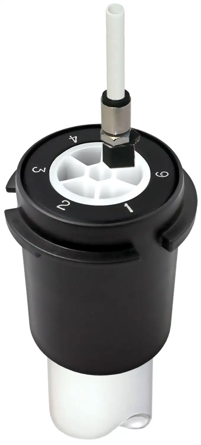
The flow through seal assembly is tightened using a 11/32″ (9 mm) wrench. Once tightened, press down on the black ring while pulling up to remove the red plug. Then push the 1/4″OD tubing into the fitting, which creates a leak proof seal.

Figure 32 – Solinst CMT Multilevel System Flow Through Seal Assembly Installed in Wellhead Manifold
