Solinst Eureka, a global leader in the design and manufacture of multiparameter water quality sondes.
Safeguard your project’s success and mitigate any potential for downtime or additional costs.
The Solinst Tag Line, (Model 103), is recommended for accurate sand and bentonite placement.

Figure 28 – Solinst CMT Multilevel System Installation Using Sand and Bentonite Layers
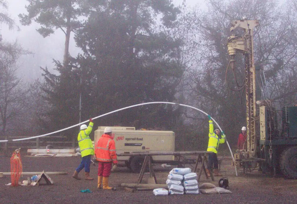
Lower the assembled CMT System into the borehole slowly.
If buoyancy is a problem, wait, as the channels below water level will slowly fill and allow the system to be lowered further. To speed this process along, pour or pump clean water into the vent holes.
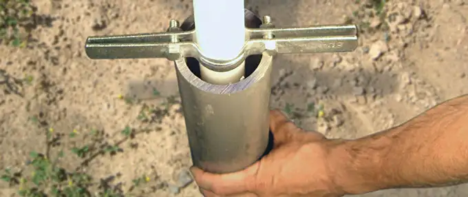
When the required depth is reached, suspend the system with the System Support Clamp (Figure 29) to prevent it from moving during well construction.
Once the backfilling operation is complete, the System Support Clamp is removed and can be reused for the next installation.

Figure 29
CMT System Support Clamp (#105603)
Avoid using “single lifts” of grout greater than 50 ft in the unsaturated zone.
Complete the installation by carefully pouring or using a tremie to place sand and bentonite at appropriate levels to seal the borehole annulus.