Configuring Tubing Bottom
Water Quality Probes
Solinst Eureka, a global leader in the design and manufacture of multiparameter water quality sondes.
Solinst Field Services
Safeguard your project’s success and mitigate any potential for downtime or additional costs.
Step 17) Insert Expansion Plugs
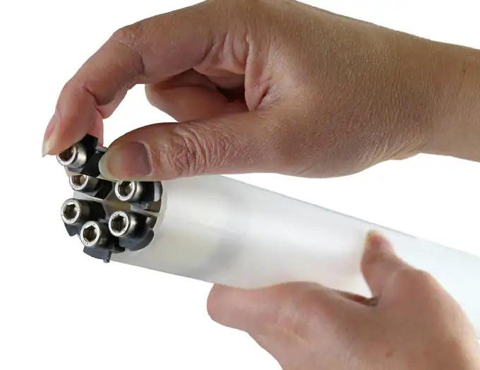
At the bottom of the CMT Multilevel System tubing, insert an expansion plug into each of the six channels. (Figure 23) Tighten each to a torque of 10 inch-pounds using the torque driver.
Note:
Port plugs are tightened to a torque of 12.5 inch-pounds. Plugs in the base, or bottom, of the CMT should be torqued sequentially and incrementally to ensure even expansion.
Step 18) Attach the Guide Point Port (#105856)
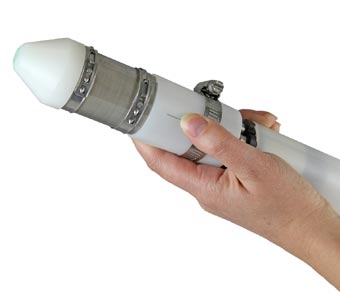
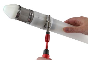
Slide the Guide Point Port Assembly (Figure 24) over the end of the CMT tubing and secure it to the tubing with the gear clamp (Figure 25). Use a torque tool and drive socket extension to thighten the gear clamp to a torque of 12.5 inchpounds. The end of the Guide Point Port Assembly is tapered to prevent the bottom of the CMT tubing from getting snagged on a rock ledge or casing joints as it is being inserted into a borehole. The end of the Guide Point Port Assembly also has threading (3/8″ – 16 UNC) to connect a weight, if desired. With the gear clamp torqued to 12.5 inch-pounds, the Guide Point Port Assembly can support up to 20 lbs of additional weight (optional).

Figure 23 – Insert CMT Multilevel System Pie Plug

Figure 24 – Installing CMT Guide Point Port

Figure 25 – Tightening CMT Oetiker clamp onto Guide Point Port
Step 19) Install an Anchor
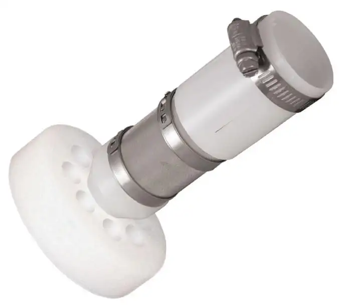
If desired, an anchor (3.75″ diameter) can be attached to the Guide Point Port using a hex bolt (Figure 26). An anchor is used during installations where it is helpful to secure the bottom of the CMT to keep it from moving during well construction. Once the tubing has been inserted, use sand placed on top of the anchor to secure the well. This will prevent it from being pulled up as drive casing or augers are withdrawn from the borehole. Holes have been drilled in the anchor to allow water in the borehole to pass through the anchor when the CMT well is inserted.

Figure 26 – CMT Guide Point Port with Anchor
